Page 48
Operation
optoNCDT 1700
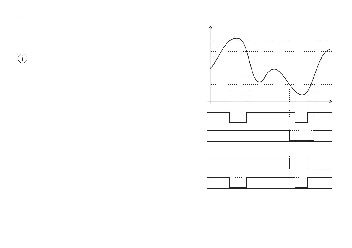
The following four values are used:
- Upper limit (UL),
- Lower limit (LL),
- Upper hysteresis value (UH),
- Lower hysteresis value (LH).
If the upper limit is exceeded the assigned
switching output 1 will be activated (conduc-
ing), and deactivated again with the follow-on
shortfall on the upper hysteresis value. The same
applies in principle to a shortfall on the lower
limit and switching output 2, see Fig. 28.
Standard setting
Upper limit (UL):
101 % FSO / Digital value: 16365
Upper hysteresis value (UH):
100 % FSO / Digital value: 16207
Lower hysteresis value (LH):
0 % FSO / Digital value: 161
Lower limit (LL):
-1 % FSO / Digital value: 0
In switch mode, both switching outputs are
activated when:
- the object to be measured is outside the mea-
surement range, see Fig. 28,
- there is no object to be measured present, or
- if the object to be measured is unsuitable (too
dark, polished metal, insufficiently reflective).
IMPORTANT!
The limit control is
based on the average.
Measured value
UL
UH
LH
LL
+
GND
+
GND
+
GND
+
GND
Switching output 1
Switching output 2
Switching output 1
Switching output 2
SET_UPPERLIMIT F1
SET_LOWERLIMIT F1
EMR
SMR
Time
Fig. 28 Signal sequence for the switching outputs in opera-
tion mode „Sync switch“ and „Trigger switch“