Page 43
Operation
optoNCDT 1700
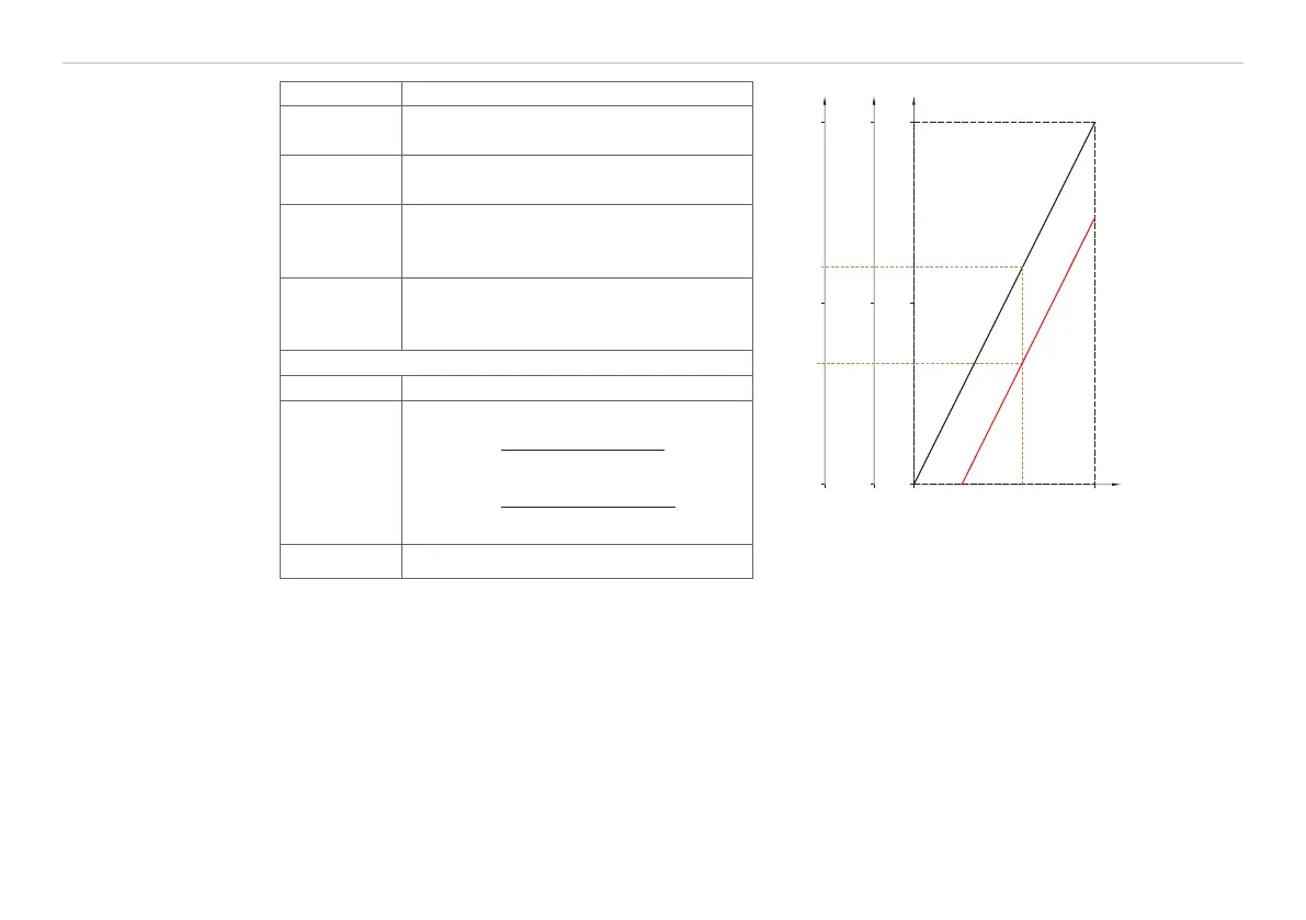
Sequence „Mastering“
0 V
5 V
10 V
100 %
x m
0 % Measurement
range
4 mA
12 mA
20 mA
161
8184
16207
Output characteristic
Output characteristic after mastering
Operation
mode
switch-mode
Setpoint
value
Programmed master value
Step 1
Move object to be measured and sen-
sor to desired position relative to one
another.
Step 2
Press Zero key once or connect the
“Zero” input to GND for 0.5 up to 3 s
or command „SetZero“
1
.
Output signals after “Mastering”
Indicator LED „zero“ lights up.
Analog
value
U
out, M
=
Master value 10 V
Measurement range
.
I
out, M
=
Master value 20 mA
Measurement range
.
Digital value D
A
= Master value Fig. 22 Characteristic for mastering
Fig. 23 Sequence for mastering
Example:
Measurement range 50 mm, voltage output 0 ... 10 V
Master value 17 mm, related to the centre of the measurement range (MR) = 5 V,
Analog value during mastering: 3.4 V
After the mastering, the sensor gives new measurement values, related to the master value. The non-mas-
tered condition applies by means of a reset.
1) Possible at Firmware version 6.0