56 Control Panel
________________________________________________________________________________________________
_______________________________________________________________________________________________
MICROPLEX Operator’s Manual LOGIJET T4 /T6 /RFID Edition 1.3
6.7. Syntax of Diagrams
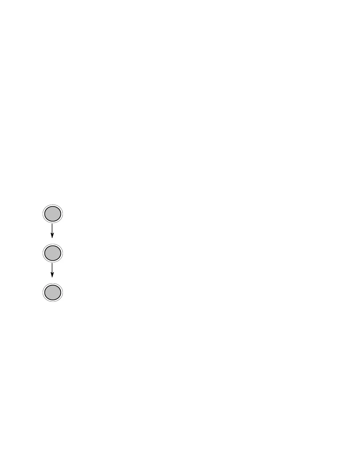
OFFL.
MENU
ENTER
["Message"]
The control panel functions will be described using diagrams.
These diagrams show the course necessary in order to activate a
certain function.
First the elements of the diagram are explained:
The sequence on the left describes which keys have to be pressed
briefly in succession.
Please note: In the lowest line of the display the current
designation of the panel keys is displayed in time. (See
section 6.4 Function of the Control Panel Elements.)
In this example the OFFLINE key has to be pressed first. Then the
OFFLINE key is released and the MENU key has to be pressed.
Then the MENU key has to be released and the ENTER key has to
be pressed.
The ″Panel display″ column shows the display messages
corresponding to the sequences listed on the left.
In the column ″Notes″ explanations to particular operational steps
are given.