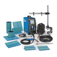
OM-278680 Page 23
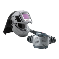
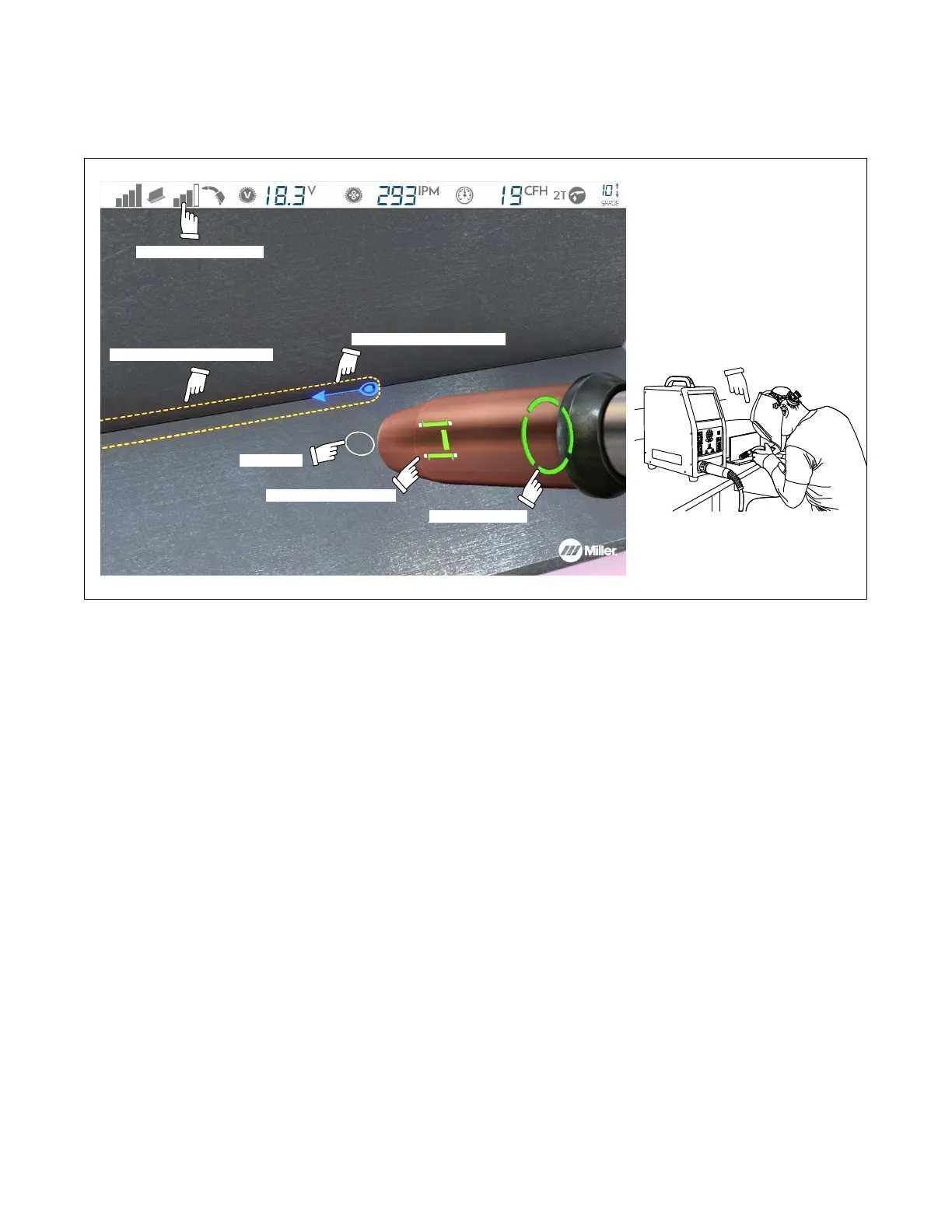
E. Determining Correct Position Of MIG Gun/Electrode And AR Helmet
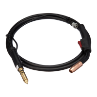
Place the gun/electrode at the simulated weld joint (visible through the helmet). The screen will display an error message if the system is not
tracking the gun/electrode. Adjust gun/electrode position, helmet lighting, and helmet position to clear the tracking error. Use the simulated guides
to help you adjust the gun/electrode angle, direction, and contact tip to work distance (CTWD) to acceptable limits. The guide(s) will display in red
if the gun/electrode is not in the correct position; guides shown in green indicate the gun position is acceptable (Figure 7-13).
Gun angle guide
Gun tracking indicator
Contact tip-work guide
Simulated weld-joint location
Use onscreen guides
to ensure correct position of
gun/electrode and helmet.
161-098
For best results, position gun so
two faces of AR tip are visible to
cameras in helmet.
Required direction of travel
Aim guide
Figure 7-13. Review Gun/Electrode Positioning Guides Before Welding
Position gun/electrode near weld joint. Pull trigger and move gun along entire length of weld joint in the correct orientation and speed as indicated
on the helmet screen. Pay close attention to on-screen guides while welding (Figure 7-14 thru Figure 7-16) and adjust technique as necessary.
Release trigger and check score (see Section F). For stick welding, when the marker block is seen to be close enough to the sticker markers on
the electrode holder, the weld simulation and electrode retraction will automatically pause. To continue, reset the electrode position within the
electrode holder and resume simulated welding.
During the weld simulation, the screen darkens to simulate the darkening of a real welding helmet. Use the up/down arrow buttons to adjust the
simulated helmet shade from 8 (lightest) to 13 (darkest), as desired.