OM-278680 Page 8
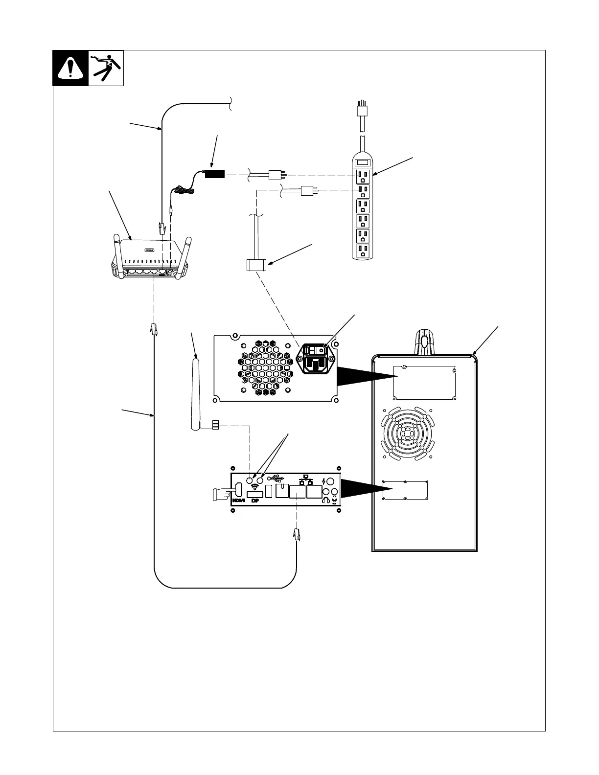
Use standalone configuration when
system is not set up with optional con-
troller.
1 Standalone Router
2 Router Power Cable
3 120 Volt 15 Amp AC Receptacle Or
Power Strip
Use of a surge-protected power strip is
recommended.
For best results, locate router within 39
in. (1 m) of simulator.
4 Simulator
5 WiFi Antenna (One Shown)
6 WiFi Receptacles
Connect both WiFi antennas to WiFi recep-
tacles on simulator.
7 Network (Ethernet) Cables (Optional)
Connect IP network cable to Internet recep-
tacle on back of router (either receptacle
can be used). Connect additional network
cable from router receptacle LAN1 to Ether-
net receptacle on back of simulator.
8 Simulator Power Cable
Connect one end of simulator power cable
to simulator. Connect other end of power
cord to 120 volt AC receptacle.
9 Input Power Switch
Place Power switch in On position.
Information on using the Teacher Soft-
ware program is provided in Section 9).
5-3. Installing The Training System − Standalone Configuration
1
6
3
5
9
8
276 687 / 161-94
2
120 V, 15A AC
IP Network
7
7
4
See Section 5-5
to connect an
external monitor
to the HDMI
receptacle.