OM-278680 Page 21
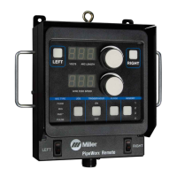
Figure 7-9. Lighting Calibration Successful
The Lighting Calibration process can be manually initiated at any point by pressing the Settings button (see Section 8-7).
D. Correcting Improper Weld Setting
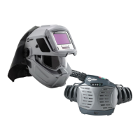
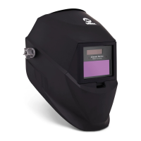
Ensure helmet illumination is on (Section 6-1).
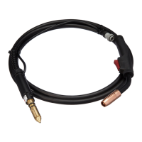
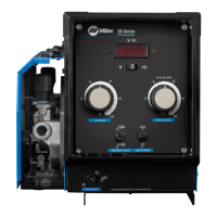
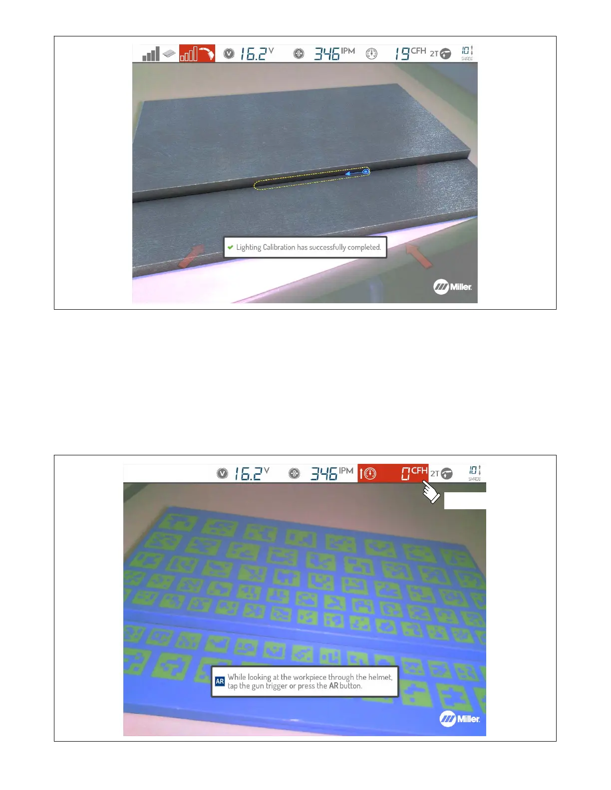
Look at the workpiece through the AR helmet and tap the gun trigger (MIG/FCAW/TIG) or press the AR button (MIG/FCAW/Stick/TIG). It may be
necessary to adjust video device settings or helmet lighting to compensate for workplace conditions (see Section 6-1). The Display Screen shows
weld voltage, wire feed speed , gas flow, trigger control selection, and other settings. Settings highlighted in red are incorrect for the application
and need to be changed. The arrows displayed on the screen indicate whether to increase or decrease the setting. Equipment settings must be
correct for the process before welding can begin (unless this default setting is overridden by instructor or administrator).
Acceptable ranges and ideal target values of settings are either preset or set by the instructor (see Section 9-3C).
Correct improper settings
shown in red (gas flow).
Figure 7-10. Example Of Improper Weld Settings