OM-278680 Page 9
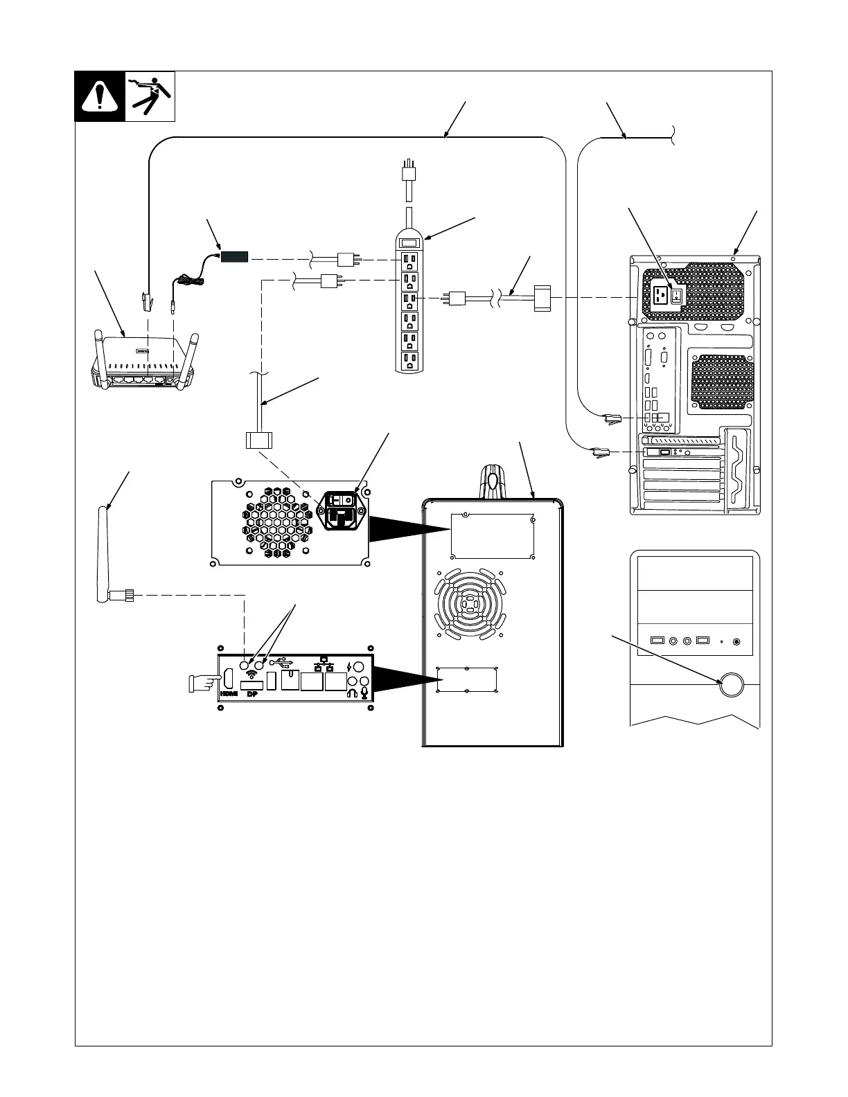
1 Classroom Router
It is very important that only the Class-
room Router is used and that all Stand-
alone Routers are not powered on.
2 Router Power Cable
3 120 Volt 15 Amp AC Receptacle Or
Power Strip
Use of a surge-protected power strip is
recommended.
For best results, locate router within 39 in.
(1 m) of simulator.
Connect one end of router power cable to re-
ceptacle on back of router. Connect other end
of cable to 120 volt AC receptacle.
Wait about 90 seconds until the WiFi signal
icon on the router is illuminated.
4 IP Network (Ethernet) Cable
5 Local AugmentedArc Network
(Ethernet) Cable
6 Controller
The controller must have the same ver-
sion of the software as the simulator (see
Section 8-3).
Connect one end of network cable to recepta-
cle LAN1 on back of router. Connect other end
of cable to Network receptacle on controller.
Connect IP network cable to internet recepta-
cle on back of controller.
7 Controller Power Cable
Connect one end of controller power cable to
120 AC receptacle on back of controller. Con-
nect other end of cable to 120 volt AC power
supply.
8 Controller Input Power Switch
Place Power switch in On position.
9 Controller Power On/Off Switch
Press and release the On/Off switch and wait
90 seconds for controller to boot up com-
pletely.
10 Simulator
11 WiFi Antenna (One Shown)
12 WiFi Receptacles
Connect both WiFi antennas to WiFi recepta-
cles on simulator.
13 Simulator Power Cable
Connect one end of power cable to simulator.
Connect other end of power cord to 120 volt
AC receptacle.
14 Simulator Input Power Switch
Place Input Power switch in On position.
Press the On/Off button on the front panel and
allow 90 seconds for simulator to boot up
completely. Change system mode to Class-
room (see Section 8-2D).
To use the teacher software in either the
classroom or standalone configuration, con-
nect a laptop or PC to the network provided by
the router.
Information
on using the Teacher Soft-
ware program is provided in Section 9.
5-4. Installing The Training System − Classroom Configuration
1
12
3
11
14
13
2
276 687 / 161-94 / 161-102
120 V, 15A AC
6
7
8
10
IP Network
(Internet)
4
Controller
Back
Controller Front
9
Local AugmentedArc Network
5
See Section 5-5 to
connect an external
monitor to the HDMI
receptacle.