OM-267357 Page 54
The SmartStinger tracks Work An-
gle, Travel Angle, Travel Speed, Arc
Length Index, Volts, and Amps.
These parameters will be graphed
and scored just as in GMAW welding.
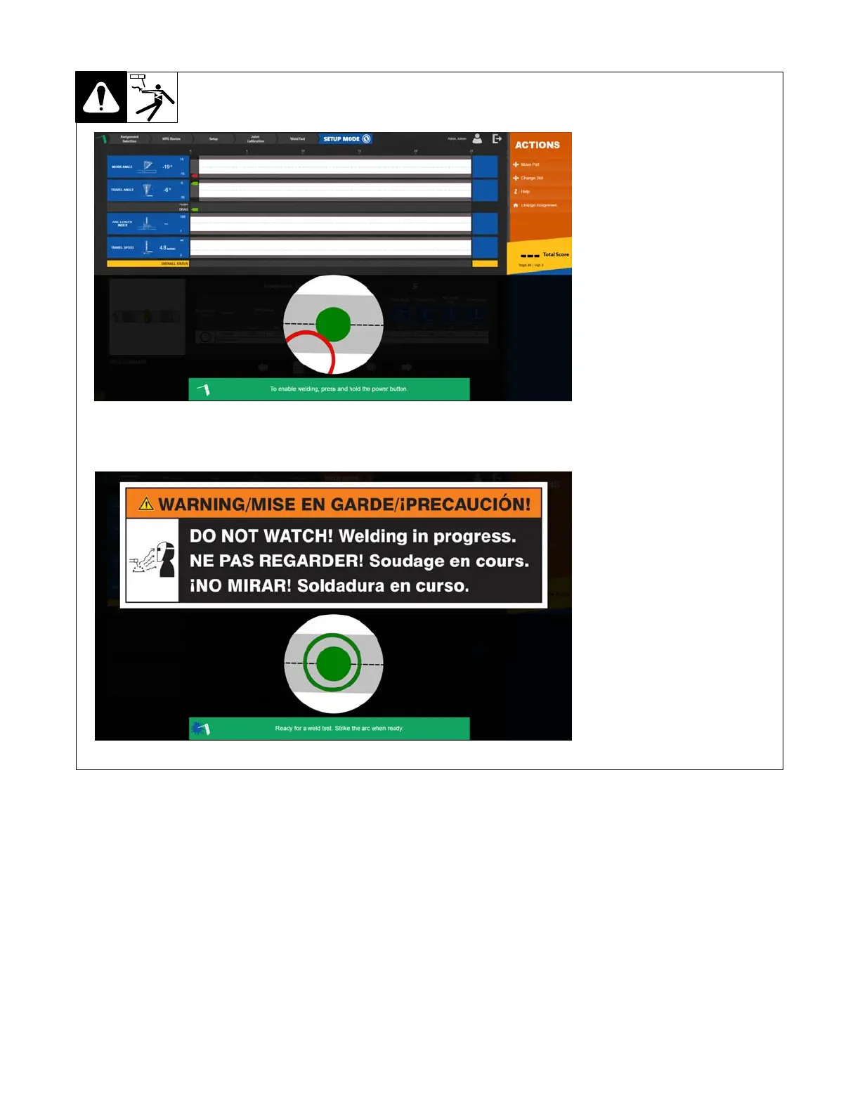
Prior to welding, the user will be pro-
vided with visual guides for Work An-
gle and Travel Angle using the touch
screen monitor. The status light on
the end of the SmartStinger provides
confirmation that both work and trav-
el angle are correct.
On the stinger, the internal vibrator
will also provide real-time feedback
on technique parameters.
Arc Length Index
Arc Length Index is a value from
0−100 that is proportional to arc
length, which is calculated using
measured arc voltage.
12-7. Using SmartStinger Position Guides
SETUP Mode
WELD Mode
12-8. Equipment Setup
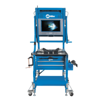
1. Assemble LiveArc training system. Install in proper location and near welding power source (see Section 5-1).
2. Ground weld table as specified in Section 5-6.
3. Connect welding power source work clamp(s) to welding table and positioning arm (if applicable). See Section 5-8.
Ensure the cables are fully threaded into the connector. Be careful not to cross−thread the connectors.
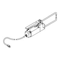
4. Use communication cable to connect router box and LiveArc. See Section 12-2.
5. Make connections between SmartStinger and router box, and welding power source and router box. See Section 12-2.
6. Connect router box to 120 volt AC receptacle. See Section 12-3.
7. Place Input Power switches in On position (on back of monitor and on side of router box). Press and hold On-Off switch on front of monitor (LED
lights) until monitor turns on.
8. Put on personal protection equipment (welding helmet, safety glasses, leather gloves, body protection, cap).
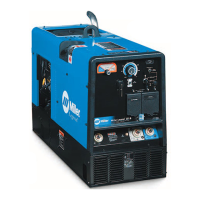
9. Turn on welding power source.