2-79
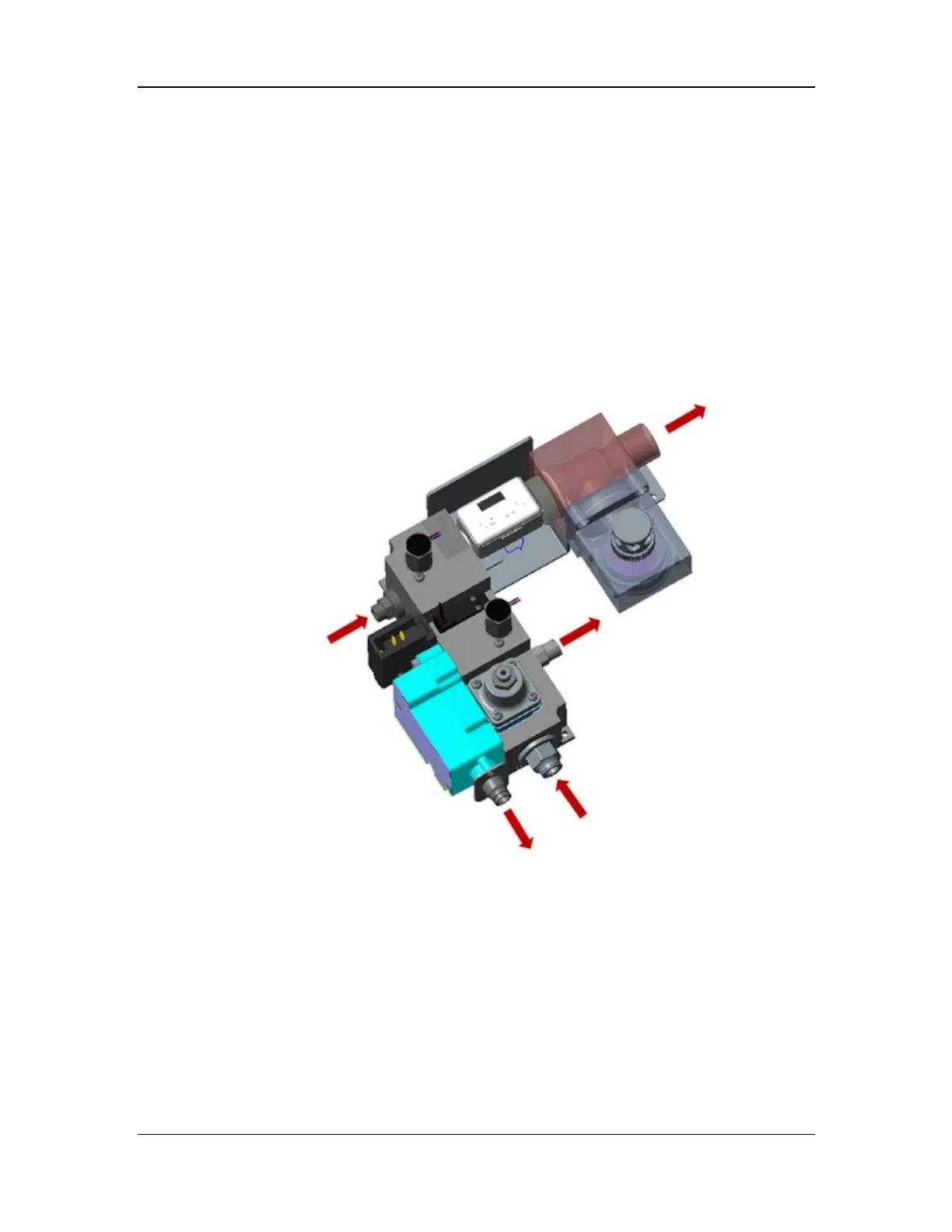
The drive gas assembly consists of the pneumatic block, flow sensor (10.4), pressure switch
(10.7), 110 cmH2O pressure relief valve (18.20), 4 cmH2O negative pressure valve (18.21), and
check valve (18.19). It is connected to other components of the anesthesia machine through the
inspiratory limb gas inlet, PEEP limb gas outlet, PEEP control gas outlet, drive gas outlet, and
PEEP exhaust port. The functions of the components are as follows: The flow sensor (10.4) is
used to monitor and feed back the gas flow output controlled by the inspiratory flow proportional
valve (10.3). The 110 cmH2O pressure relief valve (18.20) is used to control the pressure of the
drive airway within the normal operating pressure, so as to avoid damage to the operating
components. The pressure relief threshold is 110±10 cmH2O. The negative pressure valve (18.21)
opens when the patient actively inhales and closes when the patient exhales, to support free
breathing. The check valve (18.19) is used to prevent reverse diffusion of the mixed gas in the
breathing subsystem from contaminating the flow sensor. The structural diagram of the drive gas
e assembly is shown below.
Figure 36 Structural diagram of the drive gas assembly
2.3.6 Auxiliary Gas Supply Subsystem
The auxiliary gas supply subsystem is used for auxiliary gas output on the patient side. It consists
of the auxiliary O2/air assembly and high-flow O2 supply assembly.
Inspiratory limb gas inlet