8-52
5. Refer to 8.1.5Remove the Instrument Panel Assembly to remove the instrument panel
assembly.
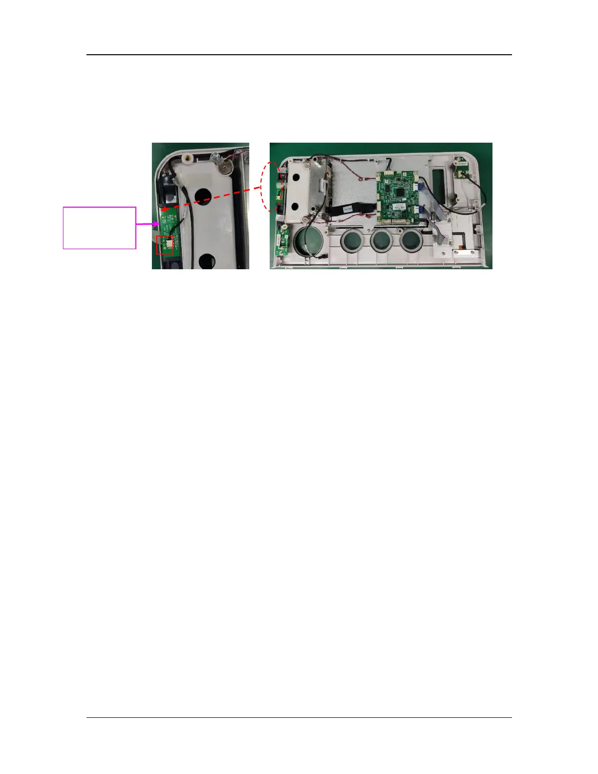
8.56.2 Remove the BFCS Switch Control Board
Disconnect the cable (marked by □ in the figure) from the BFCS switch control board and
horizontally pull out the BFCS switch control board.
8.57 Disassemble the BFCS Door Assembly
8.57.1 Prepare for Disassembly
8.57.1.1 Tools
During parts disassembly and replacement, the following tools may be required:
Phillips screwdriver
8.57.1.2 Preparations
Before disassembly,
Make sure that the anesthesia machine is turned off and disconnected from the A/C power
source.
Maneuver the anesthesia machine to an appropriate location and then apply the brake.
8.57.1.3 Pre-disassembly
1. Refer to 8.1.1Open the Service Door to open the service door.
2. Refer to 8.1.2Remove the Auxiliary Output Assembly to remove the auxiliary output
assembly.
3. Refer to 8.1.3Remove the Rear Cover Plate of the Work Surface to remove the rear cover
plate of the work surface.
4. Refer to 8.1.4Remove the Work Surface Cover Plate FRU to remove the work surface
cover plate.
5. Refer to 8.1.5Remove the Instrument Panel Assembly to remove the instrument panel
assembly.
8.57.2 Remove the BFCS Door Assembly
1. Disconnect the cable (marked by □ in the figure) from the BFCS switch control board.
2. Remove the two screws from the BFCS door assembly with the Phillips screwdriver, take
out the upper cover plate, and gently remove the BFCS door assembly. Note that there is a
torsion spring.
control board