2-67
2.3.3.2 BFCS Assembly
The BFCS assembly is used in case of system failure or EFCS assembly failure resulting from
power failure. The BFCS contains two branches: air branch and O2 branch, which are separately
controlled by two needle valves. The gas is supplied by the system switch assembly. The rear
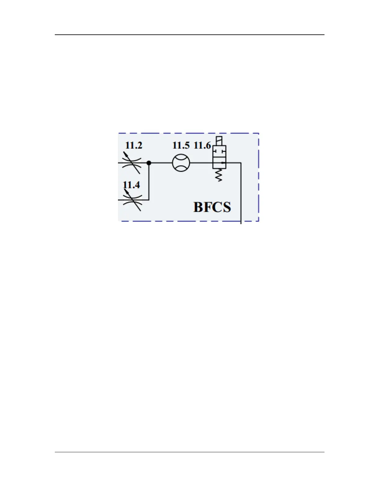
ends of the air needle valve (11.4) and O2 needle valve (11.2) are joined and connected to the
backup flowmeter (11.5), which is a mechanical float flowmeter for indicating the current flow.
The downstream is connected to the EFCS assembly through an NO switch valve (11.6), which is
powered on and closed during normal operation. When the BFCS assembly is activated, the valve
is powered off and automatically open for ventilation. The backup flowmeter is configured with a
backlight board on the rear, which emits light after the BFCS assembly is activated. The
pneumatic diagram of the BFCS assembly is shown below.
Figure 15 Pneumatic diagram of the BFCS assembly
2.3.4 Vaporizer Subsystem
The vaporizer subsystem is mainly used to provide the patient with anesthetic gas at certain
concentration. Different vaporizer subsystems are configured for the A8 and A9 anesthesia
machines. The vaporizer subsystem of the A8 anesthesia machine consists of a mechanical
vaporizer and a mechanical vaporizer manifold assembly. The vaporizer subsystem of the A9
anesthesia machine consists of an electronic vaporizer and an electronic vaporizer manifold
assembly.
2.3.4.1 Mechanical Vaporizer Manifold Assembly (for A8)
The mechanical vaporizer manifold assembly provides a mounting location for the mechanical
vaporizer (installation mode: Selectatec), mixes the anesthetic gas with the O2/air mixture at the
input end to form fresh gas, and delivers the fresh gas to the common gas outlet. The assembly
contains two connectors: one gas inlet connected to the EFCS assembly outlet, and one common
gas outlet serving as an inlet of the ACGO assembly.
In principle, the mechanical vaporizer manifold assembly is a combination of a series of
two-position three-way valves, which are controlled by the springs and vaporizer. When the
vaporizer is not installed, the valves are in a certain state due to the spring force, and the
mechanical vaporizer manifold assembly is a path. When the vaporizer is installed, the status of
the two-position three-way valves switches to make the gas flow through the vaporizer. The
pneumatic diagram is shown below.