BeneVision N1 Patient Monitor Operator’s Manual 7 - 17
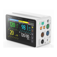
The following figure shows the ST Graphic when ST Alarm Mode is set to Absolute. The height of the bar
indicates the ST deviation value of corresponding ST lead. The color of the bar indicates ST alarm status: green
indicates that corresponding ST deviation value is within alarm limits; cyan, yellow and red indicate that the ST
deviation value exceeds the alarm limits. The color matches ST alarm priority.
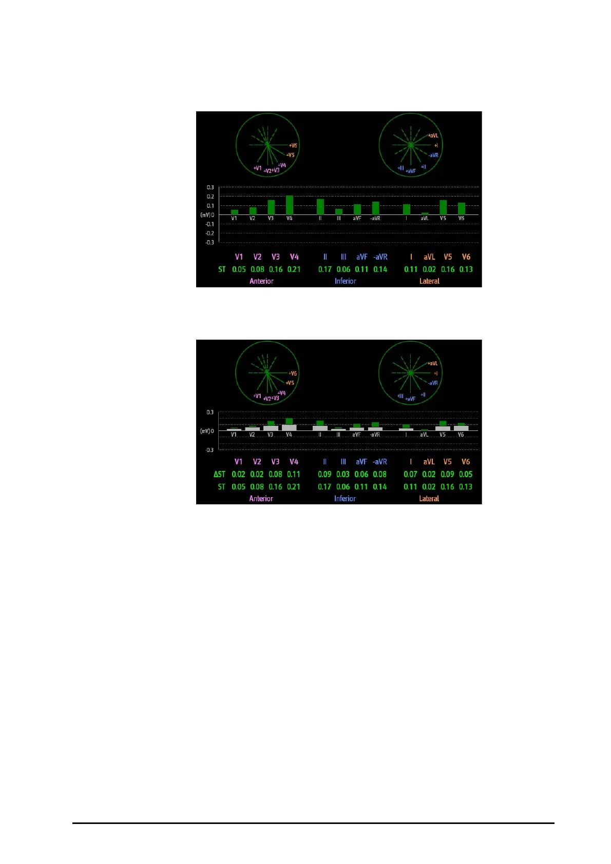
The following figure shows the ST Graphic when ST Alarm Mode is set to Relative. The height of grey bar
indicates the baseline ST deviation value and the green bar (cyan, yellow or red if an alarm occurs) indicates
relative ST from that baseline.
7.7.8 Changing ST Settings
7.7.8.1 Setting ST Alarm Properties
To set ST alarm properties, follow this procedure:
1. Select the ECG numeric area or waveform area to enter the ECG dialog.
2. Select the ST tab→ Alarm tab.
3. Set ST Alarm Mode to Absolute or Relative.
◆ Absolute: you can separately set the alarm properties for each ST alarm for each lead.
◆ Relative: you can set the alarm properties for ST Single and ST Dual alarms.
4. Set ST alarm properties.
7.7.8.2 Changing Leads for ST Display
The monitor automatically selects the three most deviated leads for ST display. You can also manually select the
leads. To do so, follow this procedure:
1. Select the ECG numeric area or waveform area to enter the ECG dialog.
2. Select the ST tab → select the Setup tab.
3. Set ST Segment. You can select up to 3 leads.