5
MEMORIES AND FILES HANDLED BY CPU MODULE
5.1 Basic Model QCPU
5.1.4 Standard RAM
5
- 11
1
Overview
2
Performance
Specification
3
Sequence Program
Configuration and
Execution Conditions
4
I/O Nunber Assignment
5
Memories and Files
Handled by CPU Module
6
Functions
7
Communication with
Intelligent Function
Module
8
Parameters
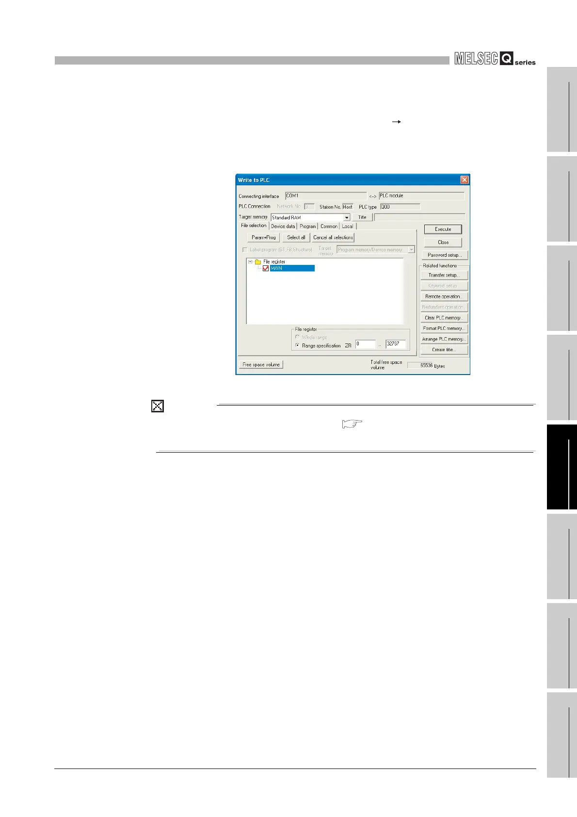
(4) Write to standard RAM
To write data to the standard RAM, choose [Online] [Write to PLC] on GX
Developer.
Select "Standard RAM" as the target memory on the Write to PLC screen and write
data to the PLC.
POINT
The file size has the minimum unit. ( Section 5.4.4)
The occupied memory capacity may be greater than the actual file size.
Diagram 5.8 Write to PLC screen
 Loading...

