9
DEVICE EXPLANATION
9.2 Internal User Devices
9.2.5 Annunciator (F)
9
- 16
9
Device Explanation
10
CPU Module Processing
Time
11
Procedure for Writing
Program to CPU Module
AppendicesIndex
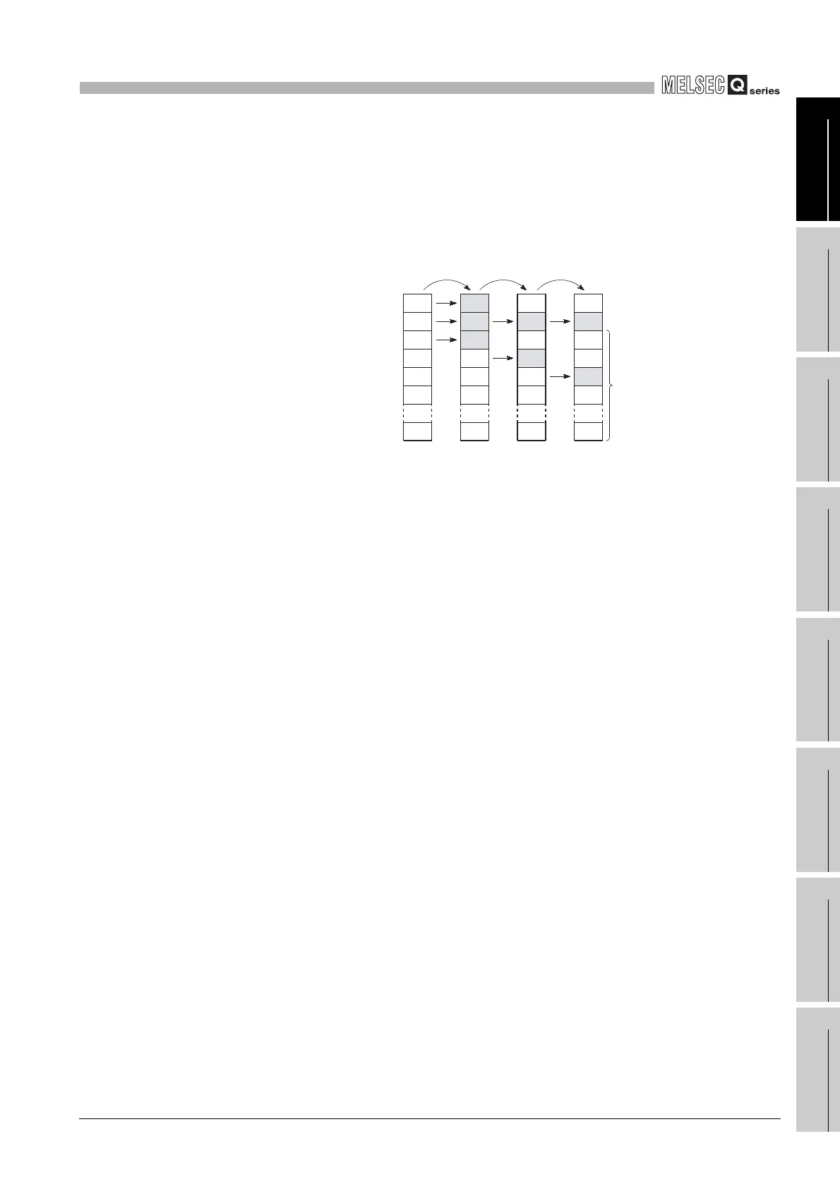
(b) Processing at annunciator ON
1) Data stored at special registers (SD62 to 79)
• Nos. of annunciators which switched ON are stored in order at SD64 to
79.
• The annunciator No. which was stored at SD64 is stored at SD62.
• "1" is added to the SD63 value.
2) Processing at CPU
• When Basic model QCPU is used
The ERR LED on the module front turns ON.
• When High Performance model QCPU, Process CPU or Redundant CPU
is used
The USER LED (red) on the module front turns ON.
3) Selection of LED ON/OFF
Setting the display priority at error occurrence to SD207 to 209 allows you to
select whether the ERR. LED is to be ON or OFF when the annunciator turns
ON.
Diagram 9.12 Processing at annunciator ON
0
0
0
0
0
0
0
SD62
SD63
SD64
SD65
SD66
SD67
SD79
50
1
50
0
0
0
0
50
2
50
25
0
0
0
50
3
50
25
1023
0
0
SET F50 SET F25 SET F1023
Up to 16 annunciator
No. can be stored.
 Loading...

