10
CPU MODULE PROCESSING TIME
10.1 Scan Time
10.1.1 Scan time structure
10
- 3
9
Device Explanation
10
CPU Module Processing
Time
11
Procedure for Writing
Program to CPU Module
AppendicesIndex
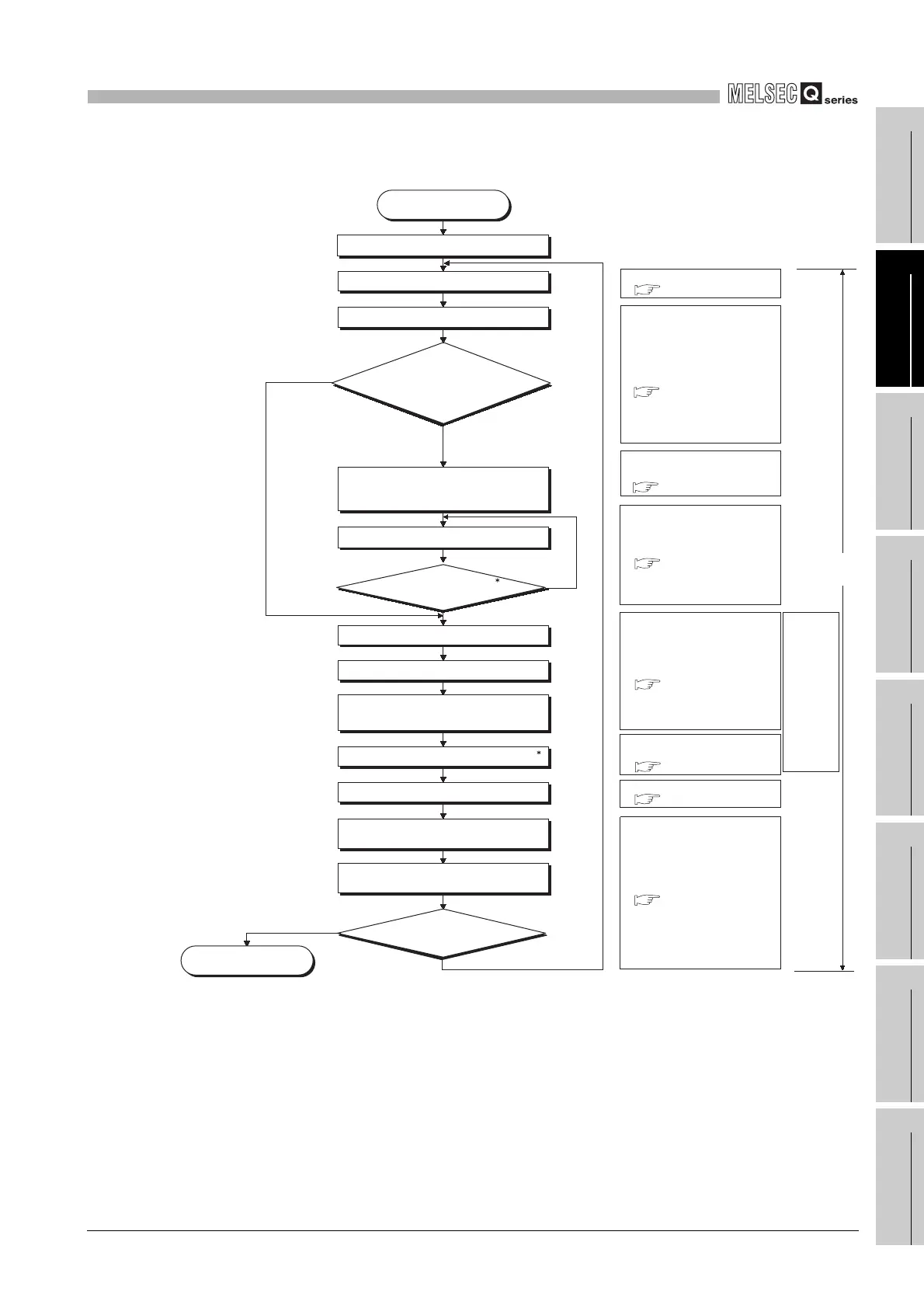
(3) Scan time structure of Redundant CPU
* 1 : Program end indicates the timing when the END, GOEND, FEND or STOP instruction is executed.
* 2 : Indicates a calendar update, program memory check processing or error clear.
Diagram 10.3 Scan time structure of Redundant CPU
Service processing time
( Section 10.1.2 (7))
NO
YES
STOP/PAUSE processing
Processing in RUN status
Program check
I/O refresh
Tracking processing
Program execution
MELSECNET/H refresh
CC-Link refresh
Constant wait processing
(No processing performed when not set)
WDT reset
scan time calculation
Operation status identification
Various function compatibility processing
3
RUN status
STOP/PAUSE status
Is program terminated?
2
Refresh by intelligent function
module parameter set on GX Configurator
Scan
time
I/O refresh time
( Section 10.1.2 (1))
Tracking processing time
( Section 10.1.2 (2))
END processing time and the
relevant instruction
( Section 10.1.2(3))
Instruction execution time
( Section 10.1.2 (4))
Module refresh time
( Section 10.1.2 (6))
Execution time of various
functions processed at END
( Section 10.1.2 (5))
Common processing time
( Section 10.1.2 (9))
END processing of DUTY instruction
(No processing performed when DUTY
instruction is not executed)
Control/Standby
system identification
Backup/Separate mode
identification
Service processing
Backup mode/Control system
Separate mode/Control system
Separate mode/Standby system
*1
Backup mode/Standby system
Common
END
processing
time
 Loading...

