APPENDICES
Appendix 2 Special Register List
App
- 40
9
Device Explanation
10
CPU Module Processing
Time
11
Procedure for Writing
Program to CPU Module
Appendices
Index
(2) System information
TableApp.20 Special register
Number Name Meaning Explanation
Set by
(When set)
Corres-
ponding
ACPU
D9
Corresponding
CPU
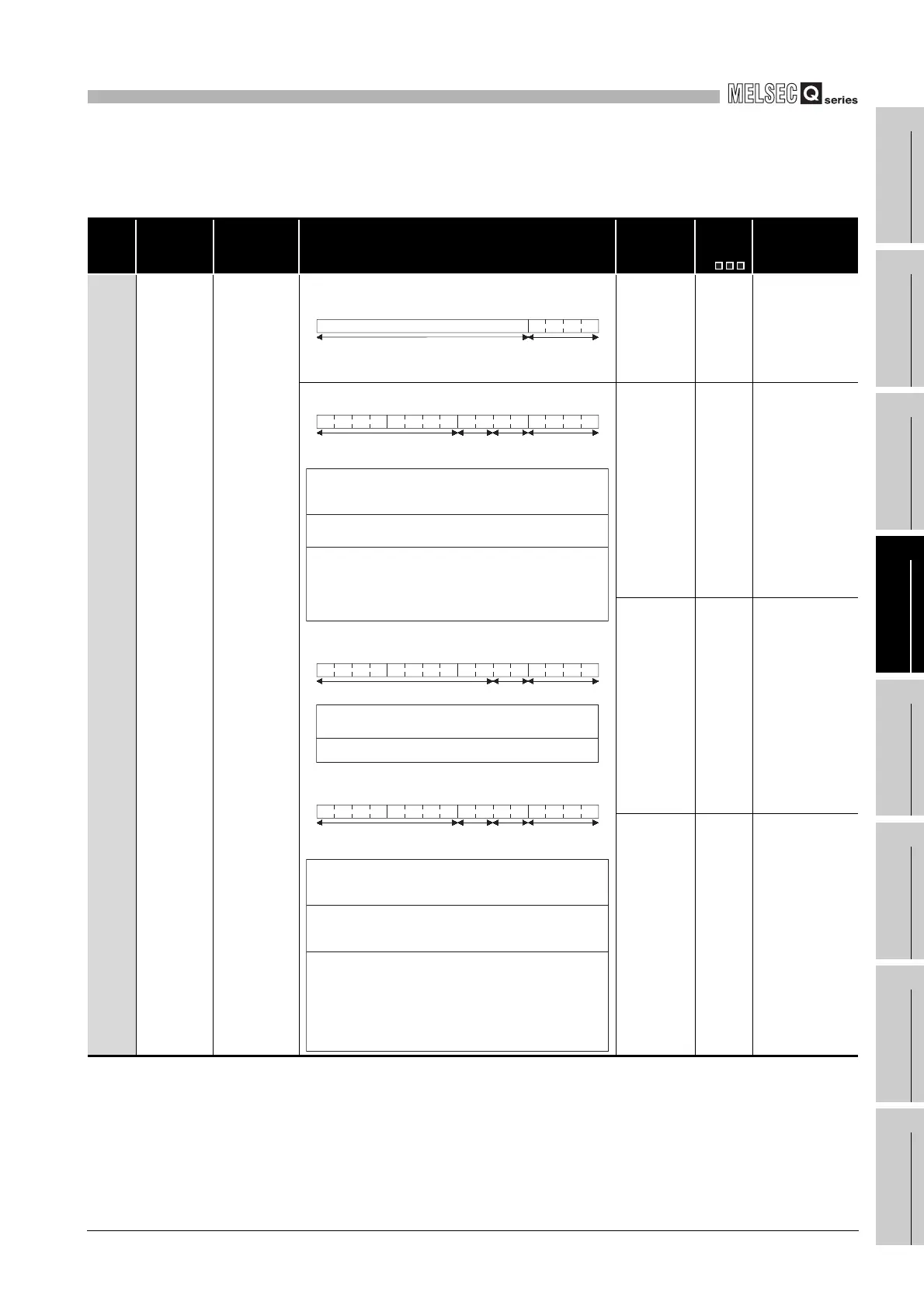
SD200 Status of switch
Status of CPU
switch
• The switch status of the remote I/O module is stored in the following
format.
1) Remote I/O module switch statusAlways 1: STOP
S (Always) New Rem
• The CPU switch status is stored in the following format:
• The CPU switch status is stored in the following format:
• The CPU switch status is stored in the following format:
S (Every END
processing)
New
Qn(H)
QnPH
QnPRH
S (Every END
processing)
New Q00J/Q00/Q01
S (Every END
processing)
New QnA
b15 b4 b3 b0
1)
Vacancy
to
to
b15 b12 b11 b8 b7 b4 b3 b0
1)
2)
Vacancy
3)
to tototo
1): CPU switch status
0: RUN
1: STOP
2: L.CLR
2): Memory card
switch
Always OFF
3): DIP switch
b8 through b12 correspond to
SW1 through SW5 of system
setting switch 1.
0: OFF, 1: ON.
b13 through b15 are vacant.
b15 b8 b7 b4 b3 b0
1)2)
Vacancy
to to
to
1): 0: RUN
1: STOP
2):
CPU switch status
Memory card switch
Always OFF
b15 b12 b11 b8 b7 b4 b3 b0
1)2)
Vacancy
3)
to tototo
1): CPU switch status
0: RUN
1: STOP
2: L.CLR
2): Memory card
switch
3): DIP switch
b8 through b12 correspond to
SW1 through SW5 of system
setting switch 1.
b14 and b15 correspond to SW1
and SW2 of system setting switch
2, respectively.
OFF at 0; ON at 1
b4 corresponds to memory card
A, and b5 corresponds to
memory card B
 Loading...

