1/2"-20 radius r od clamp bolt
Tighten to a dry level of 85 lb-ft of torque
5/8"-18 radius r od clamp bolt
Tighten to a dry level of 170 lb-ft of torque
1"-14 radius r od attachment bolt
Tighten to a dry level of 720 lb-ft of torque
Axle Clamp Group and Springs
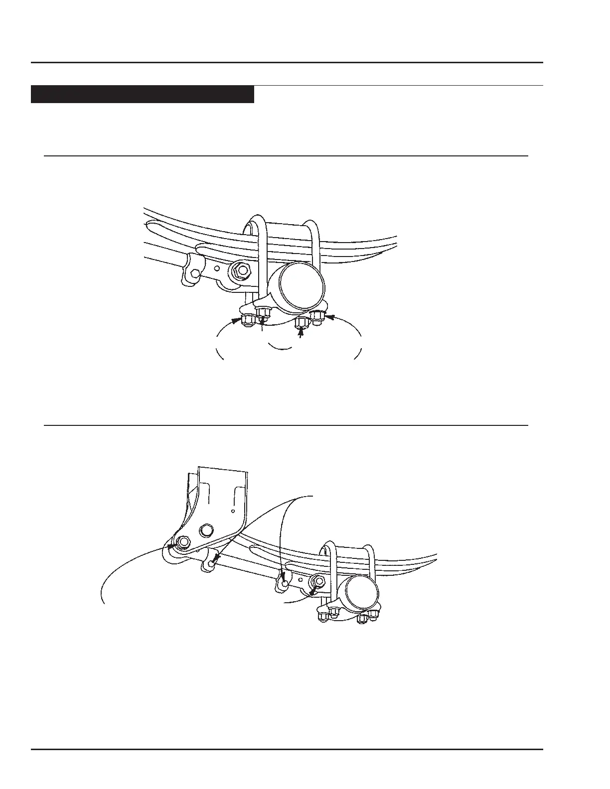
1. Check the torque on the U-bolt nuts by alternately tightening opposing cor ners of the clamp assembly. See Figur e 1.
a. When using 7/8" – 14 U-bolts, the nuts should be torqued to a dry level of 470 lb-ft.
b. When using 3/4" – 16 U-bolts, the nuts should be torqued to a dry level of 420 lb-ft.
Loose operation of this bolt can result in wear requiring that new components be installed to avoid structural damage. During
your visual inspection, if you observe any visible wear or loosening in the bushing, it is imperative that you immediately replace
the radius rod bushing and bolt. Failure to replace these components will result in damage to the hanger, spring seat, and/or
radius rod.
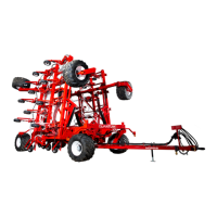
2b. Next check the 1/2" – 20 radius rod clamp bolt, whic h should be tightened to a dry level of 85 lb-ft of torque.The 5/8" –
18 radius rod clamp bolt should be tightened to a dry level of 170 lb-ft of torque. See Figur e 2. If the clamp bolt has not
been properly maintained, then wear between the radius rod screw and the eye end may be observed. If so, then the entire
radius rod must be replaced. Simply re tightening or replacing the clamp bolt will not corr ect the pr oblem.
Always carefully inspect the spring and axle clamp components for any signs of wear or cracks, and replace if visible wear or
cracks are present.
Radius Rods
2a. The 1" – 14 radius rod attachment bolts at the hangers and spring seats should be tightened to a dry level of 720 lb-ft of
torque on both the adjustable and non-adjustable radius rods. See Figur e 2.
Fig. 1
Move to opposite corner
1st
3r d
4th
2nd
Fig. 2