6-88 Manual # 42-02-2223
Troubleshooting
ICE-CTP-2 Cartop Diagnostics
There are eight diagnostic LEDs on the CTP-2 board. On power up or reset, these LEDs will
light sequentially, first in one direction, then the other, after which they will briefly clear.
Diagnostic LED 1 Regardless of the switch settings, LED 8 is ON when an interrupt is
being serviced. In normal operation it turns on and off quickly enough that it is almost as bright
as a fully illuminated LED. If LED 8 stays OFF, it indicates that the board is not functioning
normally and should be reset (press the RESET button).
If there is a problem with communication between the iBox and the CTP-2 board after initial
installation, verify that the iBox TX+ and TX- terminals are connected to the CTP-2 board RX+
and RX- terminals, and the iBox RX+ and RX- terminals are connected to the CTP-2 board TX+
and TX- terminals (see “ICE-CTP-2 Board Connections” on page 6-88).
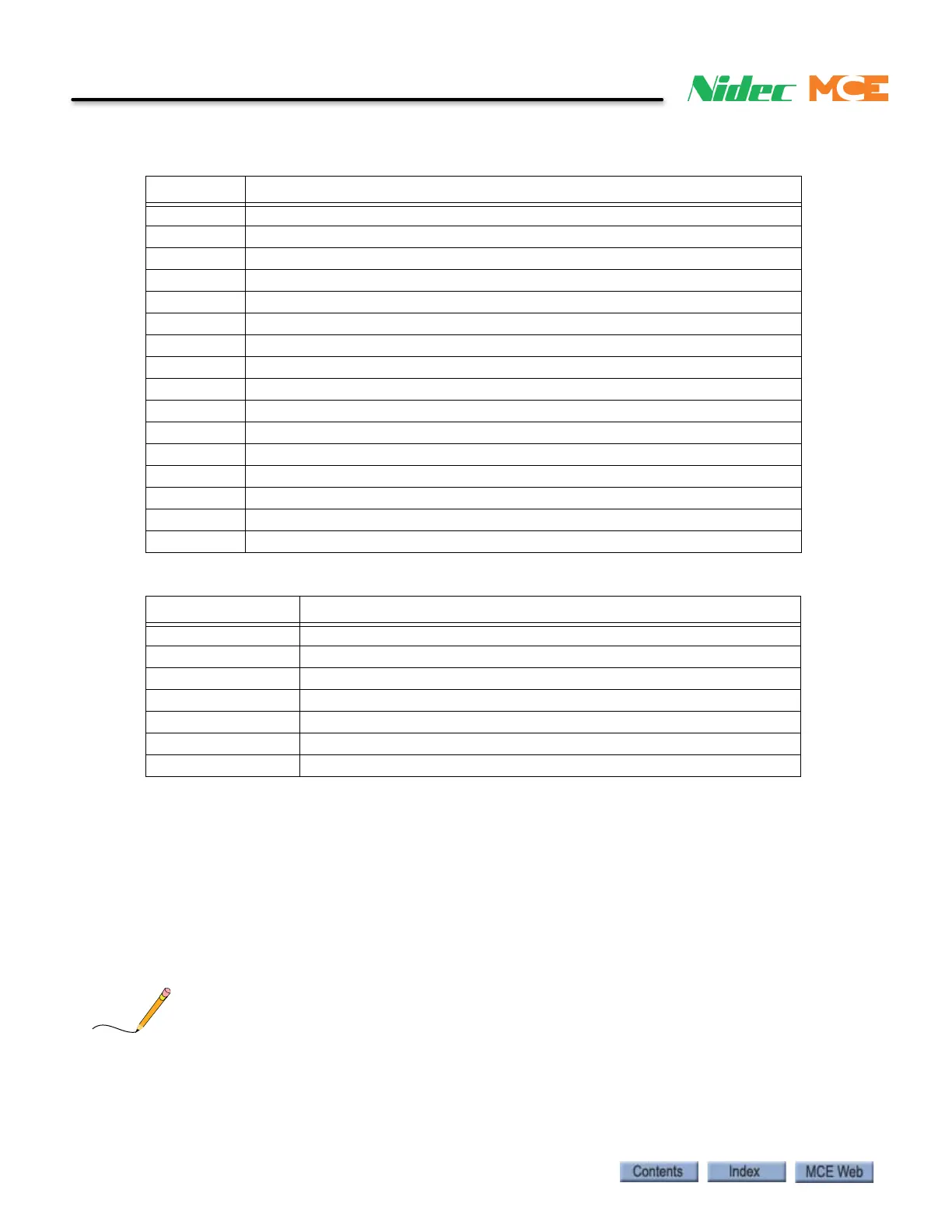
Table 6.2 ICE-CTP-2 Board Connections
Terminal Description
SHLD Shield: Common
+26V 26V output to load weigher
LW- Input from Load Weigher (analog voltage)
LW+ Input from Load Weigher (analog voltage)
DP2- Position input from iLand (balanced pair with DP2+)
DP2+ Position input from iLand (balanced pair with DP2-)
SHLD Shield: Common. Wire from shield associated with DP2.
DP1- Position input from iLand (balanced pair with DP1+)
DP1+ Position input from iLand (balanced pair with DP1-)
SHLD Shield: Common. Wire from shield associated with DP1
TX+ Transmit to iBox (connect to iBox terminal RX+)
TX- Transmit to iBox (connect to iBox terminal RX-)
SHLD Shield: Common. Wire from shield associated with TX.
RX+ Receive from iBox (connect to iBox terminal TX+)
RX- Receive from iBox (connect to iBox terminal TX-)
SHLD Shield: Common. Wire from shield associated with RX.
Table 6.3 ICE-CTP-2 Board Testpoints
Test point State
GND (x4) Ground test points
Volt (x8) +3.3, +E3.3, +5, -15, +15, -26, +26V
LW Measured from LW to TP_LW, 0.3 — 1.0 VDC = Empty car.
LW- Measured from LW- to TP_L@, -0.3 — -1.0 VDC = Empty car.
TP_LW Measured from TP_LW to GND, 4 — 8 VDC = Full car.
RSTOUT 0V= computer reset
CLKOUT Microprocessor clock