6802800U74-AN
Chapter 4: Hardware Installation
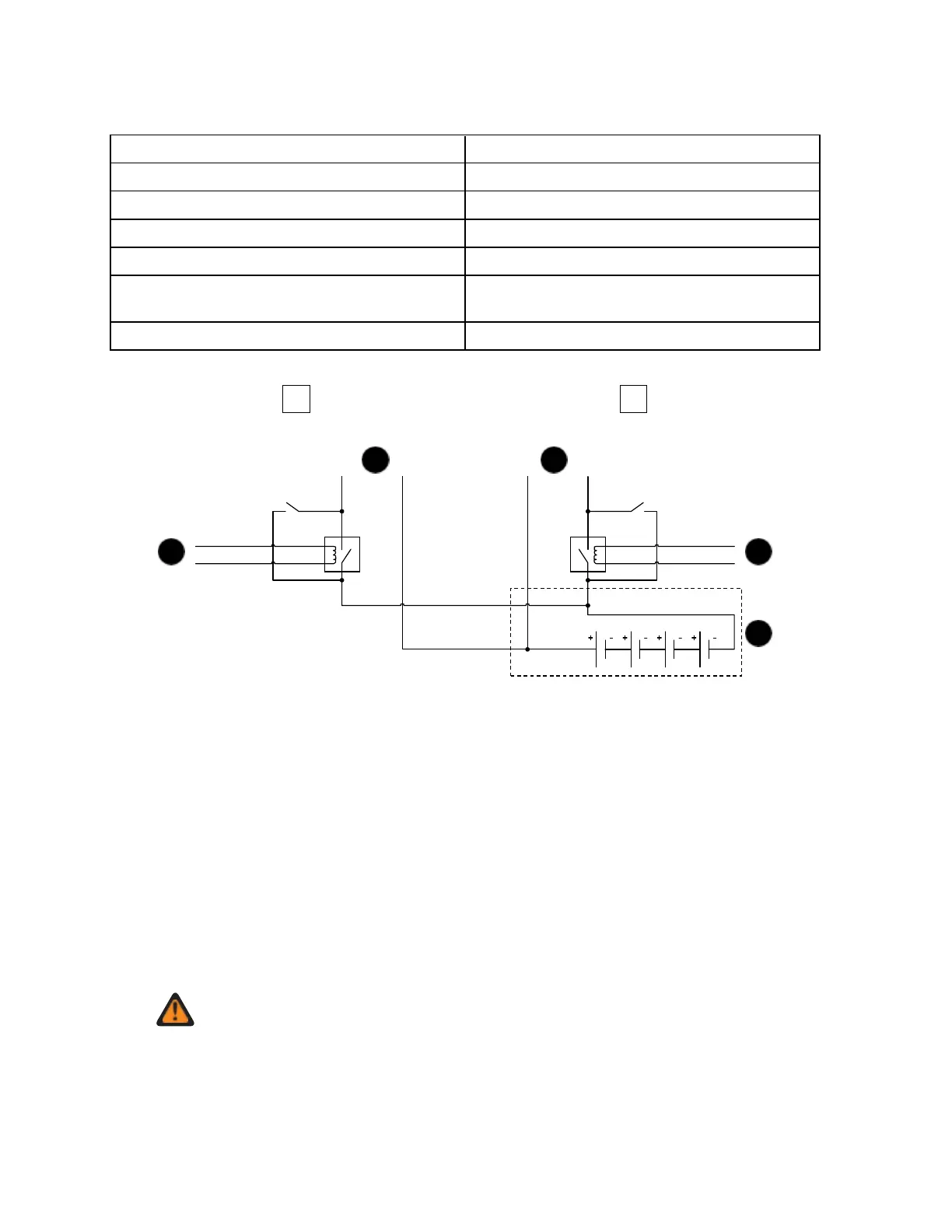
Figure 50: MTS LVD Kit Relay Connection Diagram – Dual PSU, Single Battery
Connect to Power 1 on Site Controller 1
To DC Main circuit breaker
To DC Main circuit breaker
Connect to Power 2 on Site Controller 1 or
Power 1 on Site Controller 2
The number of LVD Kits used depends on the type of MTS:
• For MTS 2, only one LVD is necessary.
• For MTS 4 with two batteries, two LVD devices have to be used (one LVD for each PSU).
• For MTS 4 powered with a single battery, LVD battery cables should be connected in parallel. LVD
controller cables should be connected to separate PSUs so each PSU controls a LVD.
• For MTS with XHUB configuration, see the first two points in this list.
4.5.3.8
Installing the MTS LVD Kit
Procedure:
1 Unpack the kit and check if all items are present.
WARNING: Working on live system is hazardous, switch off power!
2 Perform the following actions:
a Connect the battery cables (Ø6 ring terminals apply) using a PH2 screwdriver.
Recommended torque is max 2 Nm.
 Loading...