6802800U74-AN
Chapter 5: Interconnection and Internal Cabling
5.3
E1 and Ethernet Cabling
E1 cabling refers to the cabling between Site Controller and the E1 connector on the Junction Panel.
Ethernet cabling refers to the cabling between Site Controller and Base Radios.
NOTICE: Either E1 or X.21 cabling is used, depending on which option is ordered.
5.3.1
E1 and Ethernet Cabling – MTS LiTE
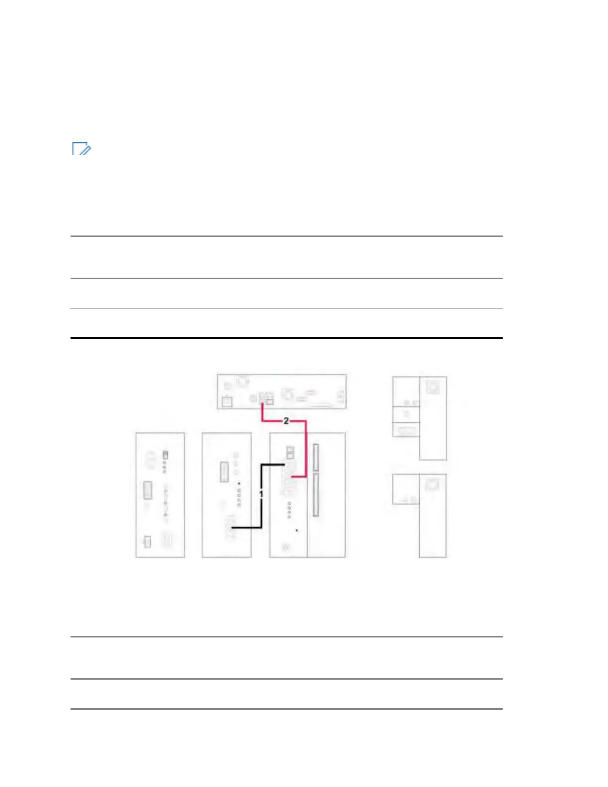
Table 40: E1 and Ethernet Cabling for MTS LiTE
In-
dex
Cable
Part
Number
From Unit/ Con-
nection Name
To Unit/ Connec-
Notes
tion Name
1 3066544B
24
Base Radio 1 /
SC1
Site Controller/
BR1
Ethernet link/ Grey cable
2 3066567B
03
Site Controller/
E1
Junction Panel/ E1 E1 link/ Green cable
Figure 96: E1 and Ethernet Cabling Diagram for MTS LiTE
5.3.2
E1 and Ethernet Cabling – MTS 2
Table 41: E1 and Ethernet Cabling for MTS 2
In-
dex
Cable
Part
Number
From Unit/ Con-
nection Name
To Unit/ Connec-
Notes
tion Name
1 3066544B
01
Base Radio 1 /
SC1
Site Controller/
BR1
Ethernet link/ Grey cable
POWER SUPPLY UNIT
FRONT VIEW
SITE CONTROLLER
REAR VIEW
AC In St atus
DC In S tatus
DC Out / Temp
PRESELECTOR
FRONT VIEW TOP VIEW
RX
Active
Mode
GPS
BTS Ala rm
Battery Temp.
Service
Sens.
SC1
 Loading...