6802800U74-AN
Chapter 4: Hardware Installation
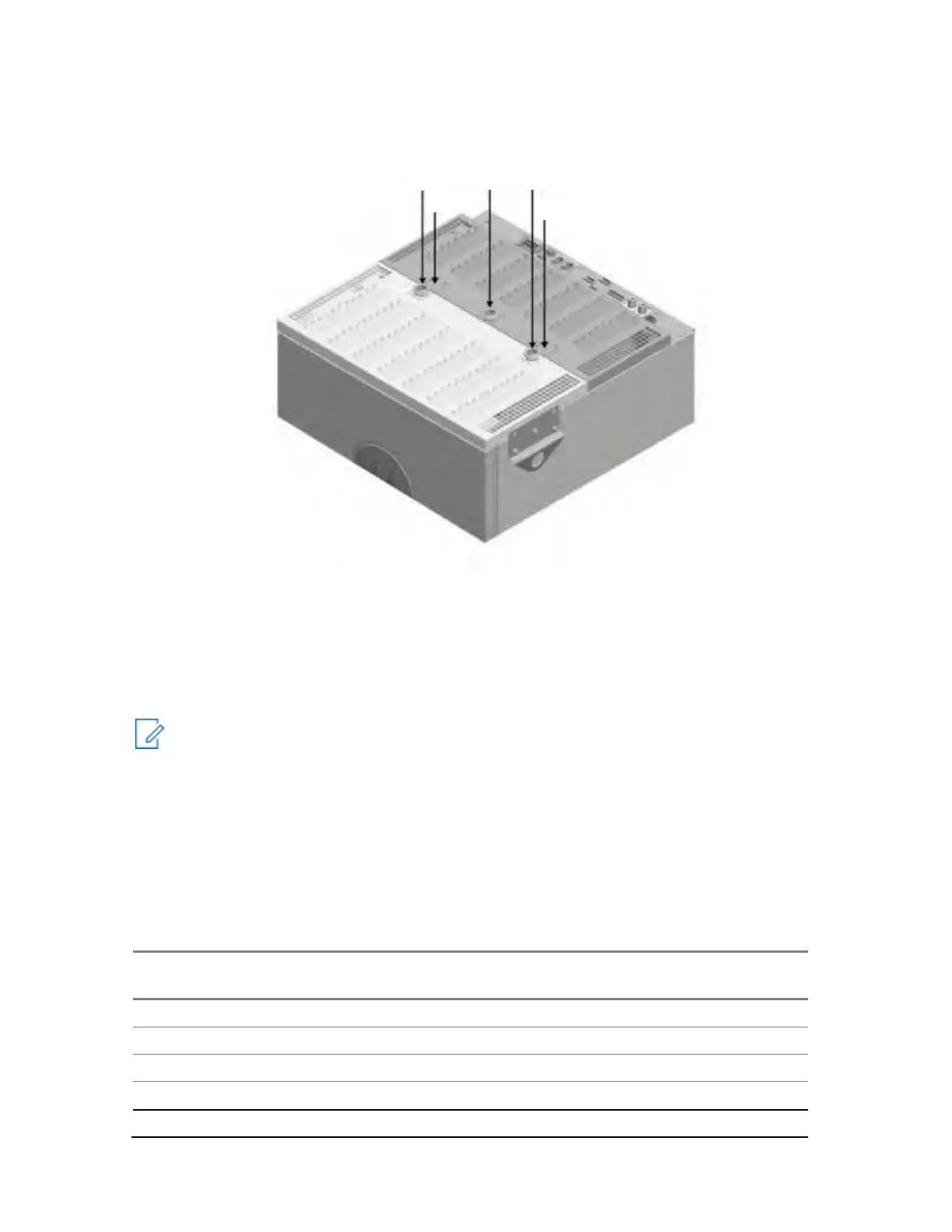
Figure 58: Base Radio Antenna Connections – MTS 4
The antenna leads should be dropped above the MTS cabinet as per the site plan. It is assumed that
the Base Radio antennas have been installed before and that the RFDS section is properly configured.
(If required, refer to chapter Interconnection and Internal Cabling on page 149, section RF Cabling on
page 177 for RF cabling diagrams.)
Identify and tag all antenna cables designated for connection to the MTS. Be sure to document this
information for future use.
NOTICE:
Proper surge protection should be installed on RF inputs to prevent potential damage to the
MTS. See Surge Arrestors and Suppliers on page 456 in Field Replaceable Units (FRUs) on
page 446 for more information.
The antenna connectors are DIN 7–16. The center connector is usually silver coated, the outer
body is usually aluminum or silver. It is recommended that mating antenna feed connectors
match metal plating correspondingly.
The screens of the antenna cables have to be grounded near to the MTS in accordance with
the R56 guidelines and national standards.
Table 20: Antenna Connections
MTS RF Antenna Configuration
Low Power
TX on 1ant., RX on 1 ant.
 Loading...