EasyManuals Logo

Motorola DIMETRA X Core User Manual

Motorola DIMETRA X Core
480 pages
To Next Page IconTo Next Page
To Previous Page IconTo Previous Page
Page #185 background imageLoading...
Page #185 background image
181
6802800U74-AN
Chapter 5: Interconnection and Internal Cabling
JUNCTION PANEL TOP VIEW
GND
DC
RGPS
X.21 User Alarms/controls
TX2/RXB
RXC
TX1/RXA
AC in
GPS
E1
FRONT VIEW
DUPLEXER
TOP VIEW
TX/RX
HYBRID COMBINER
FRONT VIEW
TX A
BR 1
BR 2
TX Out
Tx
TX B
CAN 1 CAN 2
BASE RADIO
Rx 1
AC In
Power 1
DC in
DC in
Rx 2
AC In Status
DC In Status
DC Out / Temp.
Rx 1
Rx 2
BR1
BR3
Rx 3
BR2
Rx 3
BR4
E1
CAN
DC Out.
Reset
Reset
Service
Exp. Cab
Fan 1
TX
AUX
Status
TX
AUX
Red
In
Red.
Out
Fan 2
Tx
Status
BR
Alarm
Status
Fan 3
Tx
Status
BR
Alarm
ATCC
DC Out
Service
Status
Battery
Temp. Sens.
Active
Mode
GPS
BTS Alarm
Service
SC1
SC1
SC2
SC2
Reset
CAN 1
GPS
CAN 2
DC in
Battery
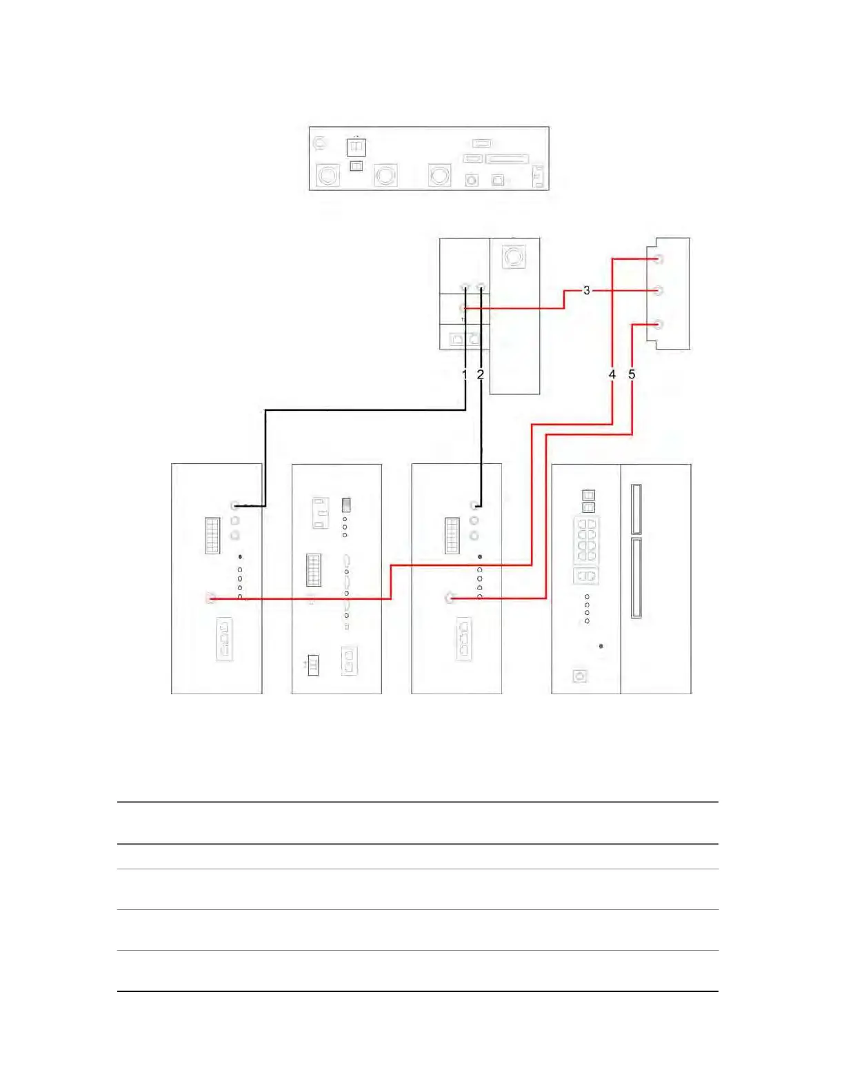
Figure 109: RF Cabling Diagram for MTS 2 with No Diversity
BASE RADIO
FRONT VIEW
POWER SUPPLY UNIT
FRONT VIEW
BASE RADIO
FRONT VIEW
FRONT VIEW
SITE CONTROLLER
REAR VIEW
POWER SUPPLY
BASE RADIO
SITE CONTROLLER
Power
Power 2
PS
5.5.5
RF Cabling – MTS 2 with One TX Antenna
Table 54: RF Cabling/Connections for MTS 2 with One TX ant. and up to Two Additional RX ant.
In-
dex
Cable Part
Number
From Unit / Con-
nection Name
To Unit / Con-
nection Name
Notes
MTS 2 - TX/RX on 1 ant.
1 3066543B
01
2 3066543B
01
3 3066543B
01
Preselector 2/ BR1 Base Radio 1/
RX2
Preselector 2/ BR2 Base Radio 2/
RX2
Preselector 1/ BR1 Base Radio 1/
RX1
RX path / RX on ANT 3
RX path / RX on ANT 3.
RX path / RX on ANT 2
Alarms/Control
X.21/Remote G

Table of Contents

Questions and Answers:

Question and Answer IconNeed help?

Do you have a question about the Motorola DIMETRA X Core and is the answer not in the manual?

Motorola DIMETRA X Core Specifications

General IconGeneral
BrandMotorola
ModelDIMETRA X Core
CategoryAccessories
LanguageEnglish

Related product manuals