EasyManuals Logo

Motorola DIMETRA X Core User Manual

Motorola DIMETRA X Core
480 pages
To Next Page IconTo Next Page
To Previous Page IconTo Previous Page
Page #181 background imageLoading...
Page #181 background image
177
6802800U74-AN
Chapter 5: Interconnection and Internal Cabling
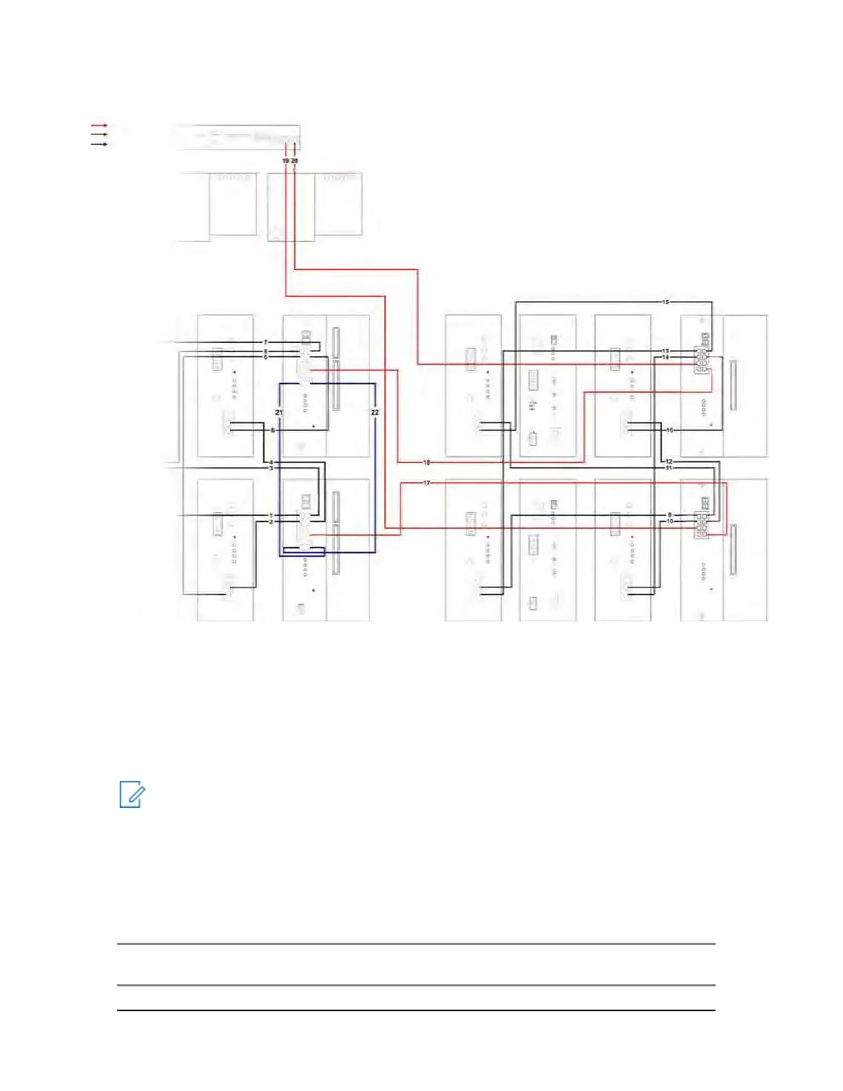
Figure 105: Ethernet Site Link Cabling for MTS 4 Expansion Cabinet with Dual Site Controller
5.5
RF Cabling
RF cabling refers to the cable connections among antenna connectors, the RF Distribution System
(RFDS), and the Base Radios and it depends on filter configuration.
RF Cabling diagrams and details for different RF configuration types are presented in subsequent
sections.
NOTICE: Not all Base Radios, filters, and associated cables are present in each configuration.
5.5.1
RF Cabling – MTS LiTE with One TX and One RX Antenna, No
Diversity
Table 50: RF Cabling/Connections for MTS LiTE with One TX and One RX ant. No Diversity
In-
dex
Cable Part
Number
From Unit / Con-
nection Name
To Unit / Con-
nection Name
Notes
MTS LiTE with One TX and One RX ant. No Diversity
Ethernet Connection
from Junction Panel
Ethernet Connection
JUNCTION PANEL TOP VIEW
AC in 1 A C in 2
RGPS1
GPS1 GP S2
User Alarm s/Controls
X.21
E1 Link 1 Link 2
RGPS2
Redundant Ethernet
TOP
PRESELECTOR
VIEW
REAR VIEW
TOP PRESELECTOR
VIEW REAR VIEW
BR1 BR2 BR3 BR4 Exp.
Cabinet
BR1 BR2 BR3 BR4 Exp.
Cabinet
RX
RX
BASE RADIO
FRONT VIEW
FRONT VIEW
SITE CONTROLLER
REAR VIEW
BASE RADIO
FRONT VIEW
POWER SUPPLY UNIT
FRONT VIEW
BASE RADIO
FRONT VIEW
XHUB CONTROLLER
FRONT VIEW
REAR VIEW
BASE RADIO
SITE CON TROLLER
BASE RADIO
POWER S UPPLY
BASE RADIO
SITE CONTROLLER
Power 2
AC In Pow er
Power 4
Rx 1
Power 1
Rx 1
DC in
Rx 1
DC in
Power 3
Rx 2
BR1
BR3
Rx 2
AC In Stat us
DC In Stat us
DC Out / T emp
Rx 2
BR5
BR6
BR7
Rx 3
BR2
BR4
Rx 3
BR8
CAN
Service
E1
Exp. Cab
Rx 3
DC Out.
DC in
Reset
TX
AUX
Status
BR
Alarm
Reset
Red
In
Red.
Out
Tx
Active
Mode
TX
AUX
Status
BR
Alarm
Tx
ATCC
DC Out
Fan 1
Status
Fan 2
Status
Fan 3
Status
Battery
Temp. Sens.
Tx
Reset
TX
AUX
Status
BR
Alarm
AUX1
Service
AUX2
Prime
Cab
GPS
BTS Alarm
Service
Service
Service
Active
Mode
GPS
BTS Alarm
SC1
Reset
SC1
SC1
SC2
SC2
Reset
SC2
CAN 1
GPS
CAN 2
DC in
Battery
BASE RADIO
FRONT VIEW
FRONT VIEW
SITE CONTROLLER
REAR VIEW
BASE RADIO
FRONT VIEW
POWER SUPPLY UNIT
FRONT VIEW
BASE RADIO
FRONT VIEW
XHUB CONTROLLER
FRONT VIEW
REAR VIEW
BASE RADIO
SITE CON TROLLER
BASE RADIO
POWER S UPPLY
BASE RADIO
SITE CONTROLLER
Power 2
AC In
Power 4
Power
Rx 1
Power 1
Rx 1
Rx 1
Power 3
DC in
DC in
DC in
Rx 2
BR3
BR1
Rx 2
Rx 3
AC In Stat us
DC In Stat us
DC Out / T emp
Rx 2
BR5
BR7
BR4
BR2
BR6
BR8
Rx 3
Rx 3
CAN
E1
AUX1
AUX2
DC Out.
Reset
Service
Exp. Cab
Reset
Reset
Service
Prime
Cab
TX
AUX
Red
In
Red.
Out
Status
BR
Alarm
Active
Mode
GPS
BTS Alarm
Tx
TX
AUX
Status
BR
Alarm
Fan 1
Status
Fan 2
Status
Fan 3
TX
Tx
ATCC
DC Out
AUX
Status
BR
Alarm
Tx
Service
Service
Status
Battery
Temp. Sens .
Active
Mode
GPS
BTS Alarm
Service
Reset
SC1
SC1
SC1
SC2
SC2
CAN 1
Reset
SC2
GPS
CAN 2
DC in
Battery
Alarms/ Control
X.21/Re mote GPS
Alarms/ Control
X.21/Re mote GPS
Alarms/Control
Alarm s/Co ntrol

Table of Contents

Questions and Answers:

Question and Answer IconNeed help?

Do you have a question about the Motorola DIMETRA X Core and is the answer not in the manual?

Motorola DIMETRA X Core Specifications

General IconGeneral
BrandMotorola
ModelDIMETRA X Core
CategoryAccessories
LanguageEnglish

Related product manuals