6802800U74-AN
Chapter 4: Hardware Installation
Figure 23: Position of Security Screws
4.4.5
Wall Fixing
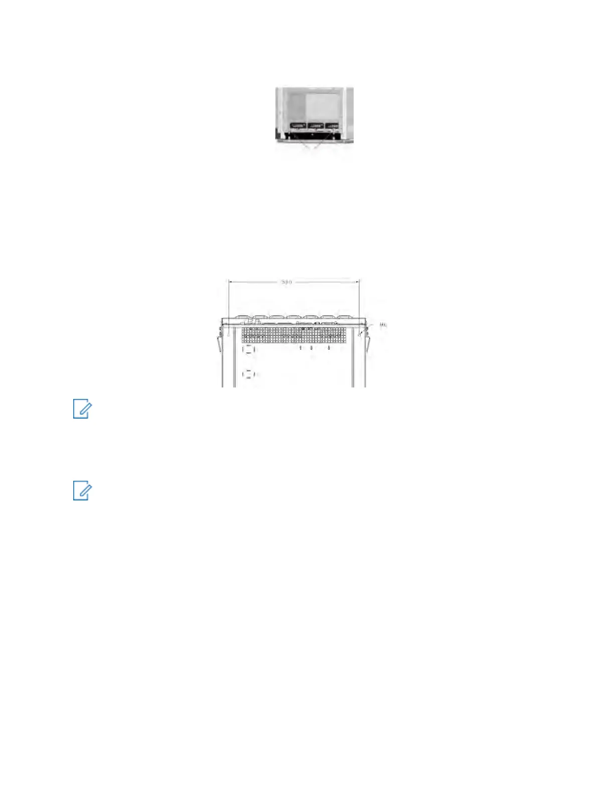
The MTS 4 and Expansion Cabinet have the option of being fixed to a wall for extra stability. To do
this, use the two M6 holes in the back of either the MTS 4 cabinet or the Expansion Cabinet. See the
following figure.
Figure 24: MTS – Wall Fixing
NOTICE: Use brackets and screws appropriate for the site wall properties.
4.5
Electrical Connections
NOTICE:
Battery backup systems are not manufactured by Motorola Solutions. Consult the
manufacturers instruction manual and other pertinent documentation for installing battery
systems. Any local regulations shall be adhered to when installing battery equipment.
The equipment cabinet is shipped with all cabling within the cabinet factory-installed. If
necessary, see Interconnection and Internal Cabling on page 149, for cabling within the cabinet.
After the station equipment mechanical installation, connect the following electrical cables:
• Grounding Cables
• Power Supply Cables
• Antenna Cables
• GPS Cables
- Remote GPS Receiver Cable
- Internal GPS Cable
• Site Link Cables
• Alarm System Cables
 Loading...