6802800U74-AN
Chapter 8: Site Controller
At initialization of the MTS, the factory configures the Site Controller with a relation between track
number and the function of the node. You can modify this configuration in a service situation.
If a node is removed or is defective, the Site Controller knows the track number of a non-responding
FRU and therefore it can make a proper service report which tells exactly what FRU to replace. When
the service is carried out, replace the track number of the defective FRU with the new track number in
the mapping list, that way the new track number is mapped to the function of the replaced FRU.
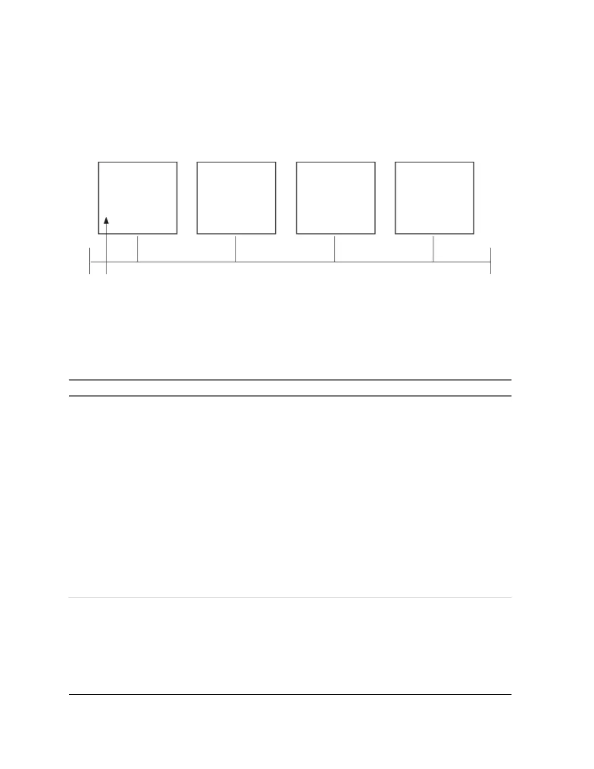
Figure 170: Site Controller - CAN Bus
Mapping List in SC
Track# Function
#543265 PSU1
#648789 DPM1
#648790 DPM2
Table 91: Site Controller - CAN Bus Functionality
Unit Function
PSU Monitoring:
• PSU temperature: -30 °C to +100 °C, tolerance: 2 °C.
• Battery current: -20 A to +10 A, tolerance: ±1%.
• Battery voltage: 30 V to 60 V, tolerance: ±1%.
• Battery temperature: -30 °C to +100 °C, tolerance: 2 °C.
• 7 V output voltage: 0 V to 10 V, tolerance: ±2%.
• 7 V output current: 0 A to 10 A, tolerance: ±2%.
• 28.5 V output voltage: 0 V to 30 V, tolerance: ±2%.
• 28.5 V output current: 0 A to 10 A, tolerance: ±2%.
• PSU output power: 0 W to 1100 W, tolerance: ±2%.
• Fan output voltage: 0 V to 30 V, tolerance: ±2%.
• PSU input air temp.: -30 °C to +100 °C, tolerance: ±2 °C.
Alarms:
• DC Source Fail: Indicating DC input voltage outside limits (below 43 V).
• DC Out Fail: DC output voltages out of limits.
• AC Source Fail: Early warning, indicating that the AC input is interrupted
and the PSU starts to operate from DC input source in 15 ms. (if a backup
source is present).
 Loading...