TROUBLE DIAGNOSIS
MTC-97
C
D
E
F
G
H
I
K
L
M
A
B
MTC
Revision: January 2005 2004 Quest
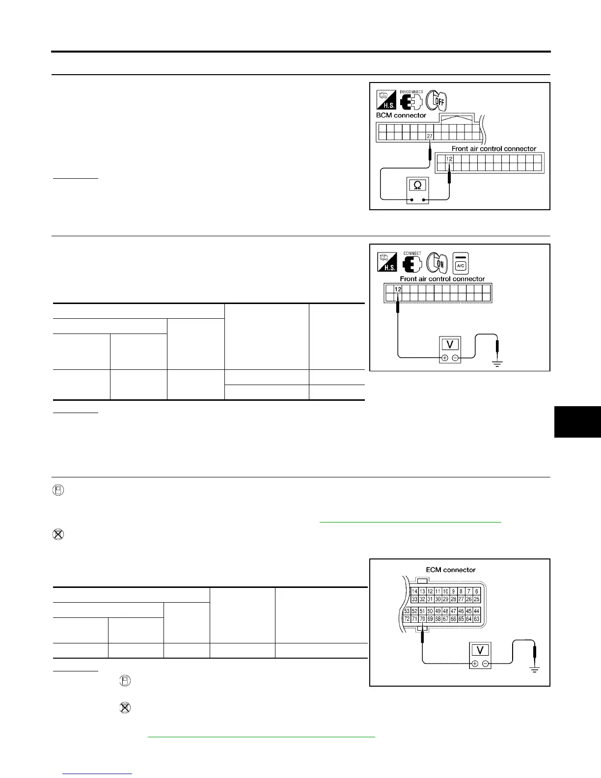
6. CHECK CIRCUIT CONTINUITY BETWEEN BCM AND FRONT AIR CONTROL
1. Turn ignition switch OFF.
2. Disconnect BCM connector and front air control connector.
3. Check continuity between BCM harness connector M18 terminal
27 (L/R) and front air control harness connector M49 terminal 12
(L/R).
OK or NG
OK >> GO TO 7.
NG >> Repair harness or connector.
7. CHECK VOLTAGE FOR FRONT AIR CONTROL (COMPRESSOR ON SIGNAL)
1. Reconnect BCM connector and front air control connector.
2. Turn ignition switch ON.
3. Check voltage between front air control harness connector M49
terminal 12 (L/R) and ground.
OK or NG
OK >> GO TO 8.
NG-1 >> If the voltage is approx. 5V when A/C switch is ON, replace front air control.
NG-2 >> If the voltage is approx. 0V when A/C switch is OFF, replace BCM.
8. CHECK REFRIGERANT PRESSURE SENSOR
WITH CONSULT-II
1. Start engine.
2. Check voltage of refrigerant pressure sensor. Refer to MTC-31, "
CONSULT-II Function (BCM)" .
WITHOUT CONSULT-II
1. Start engine.
2. Check voltage between ECM harness connector F54 terminal
70 (W) and ground.
OK or NG
OK >> ● WITH CONSULT-II
GO TO 9.
● WITHOUT CONSULT-II
GO TO 10.
NG >> Refer to EC-682, "
REFRIGERANT PRESSURE SENSOR" .
Continuity should exist.
WJIA0974E
Terminals
Condition
Voltage
(Approx.)
(+)
(-)
Front air
control con-
nector
Terminal No.
(Wire color)
M49 12 (L/R) Ground
A/C switch: ON 0V
A/C switch: OFF 5V
WJIA0449E
Ter minals
Condition
Voltage
(Approx.)
(+)
(-)
ECM con-
nector
Terminal No.
(Wire color)
F54 70 (W) Ground A/C switch: ON 3.6 - 3.88V
LJIA0124E