EasyManuals Logo

Netafim nmc-pro Installation Guide

Netafim nmc-pro
167 pages
To Next Page IconTo Next Page
To Previous Page IconTo Previous Page
Page #164 background imageLoading...
Page #164 background image
NMC-PRO Installation Manual
164Page
TECHNICAL SPECIFICATIONS
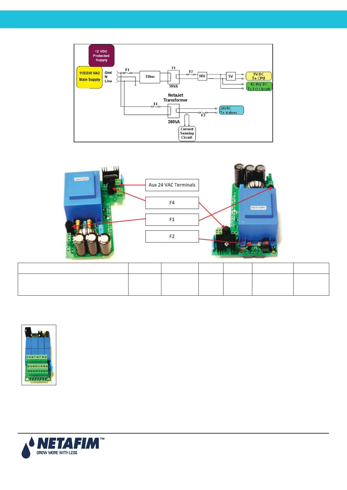
18.2.3.1 Power Supply Circuit Drawing
18.2.3.2 Power Supply Fuse Protection
Location Designation Type Style Rating Reaction Time Dimensions
NMC-PRO Power Supply, Main Transformer T1
F1
Tubular Glass
M205
1.0 Amp
Slow Blow (T)
20mm x 5mm
NMC-PRO Power Supply, CPU & I/O Circuit
F2
Tubular Glass
M205
4.0 Amp
Slow Blow (T)
20mm x 5mm
NMC-PRO Power Supply, 24VAC Output Circuit*
F3
Thermal
9.0 Amp
Thermal
NMC-PRO Power Supply, Output NetaJet Trans.
F4
Tubular Glass
M205
1.25 Amp
Slow Blow (T)
20mm x 5mm
* Back side of power supply card
18.2.3.3 Output
24 VAC / output card
8 x D.O. AC Relay
Output rating = 5 Amps
Single output changing rate = 0.4 Sec

Table of Contents

Other manuals for Netafim nmc-pro

Questions and Answers:

Question and Answer IconNeed help?

Do you have a question about the Netafim nmc-pro and is the answer not in the manual?

Netafim nmc-pro Specifications

General IconGeneral
BrandNetafim
Modelnmc-pro
CategoryController
LanguageEnglish

Related product manuals