Enable 802.1Q VLAN: Allows enable/disable VLAN configuration.
Interface: WAN/LAN – This drop box allows the selection of the interface (WAN or LAN) in which
the VLAN will be created.
802.1Q VID: Insert the VID (VLAN ID).
VLANS: List of VLANs already created.
VLAN application examples:
1. Mark the AP client‟s traffic with VID 3.
The traffic that passes through an Access Point that is able to mark (tag) the Ethernet
frames with a given VID (3, for example) are forwarded to the switch where the Access
Point is connected to. That switch‟s port must be marked as a member of the same VLAN
used by the AP to mark the traffic (VID 3). Furthermore, this traffic will then be forwarded
to the switch port where the WGS5000‟s LAN interface is connected to. Therefore the
WGS5000 must be VLAN capable and have an interface marked as a member of the same
VLAN (VID 3). IF the AP‟s traffic is marked with VID 3, the WGS5000‟s configuration will be:
LAN|3|Bridge.
2. To configure the functionality to ping network equipments, for example, ping an AP that
uses VLANs. Generally, management AP traffic uses a unique VLAN. To accomplish this task
(ping the AP), the same VLAN must be configured on the AP, on the switch and on
WGS5000 – so that the WGS5000 can gain access to AP management. Take this example:
the AP is using VLAN with VID 4 for management traffic. The switch port that connects to
the AP is marked as a member of VID 4. The WGS5000 must have an interface marked as
a member of VID 4 and the configuration will be: LAN|4|IP| 192.168.186.1, where the IP
address assigned to the VLAN must be in the same range of AP‟s IP address.
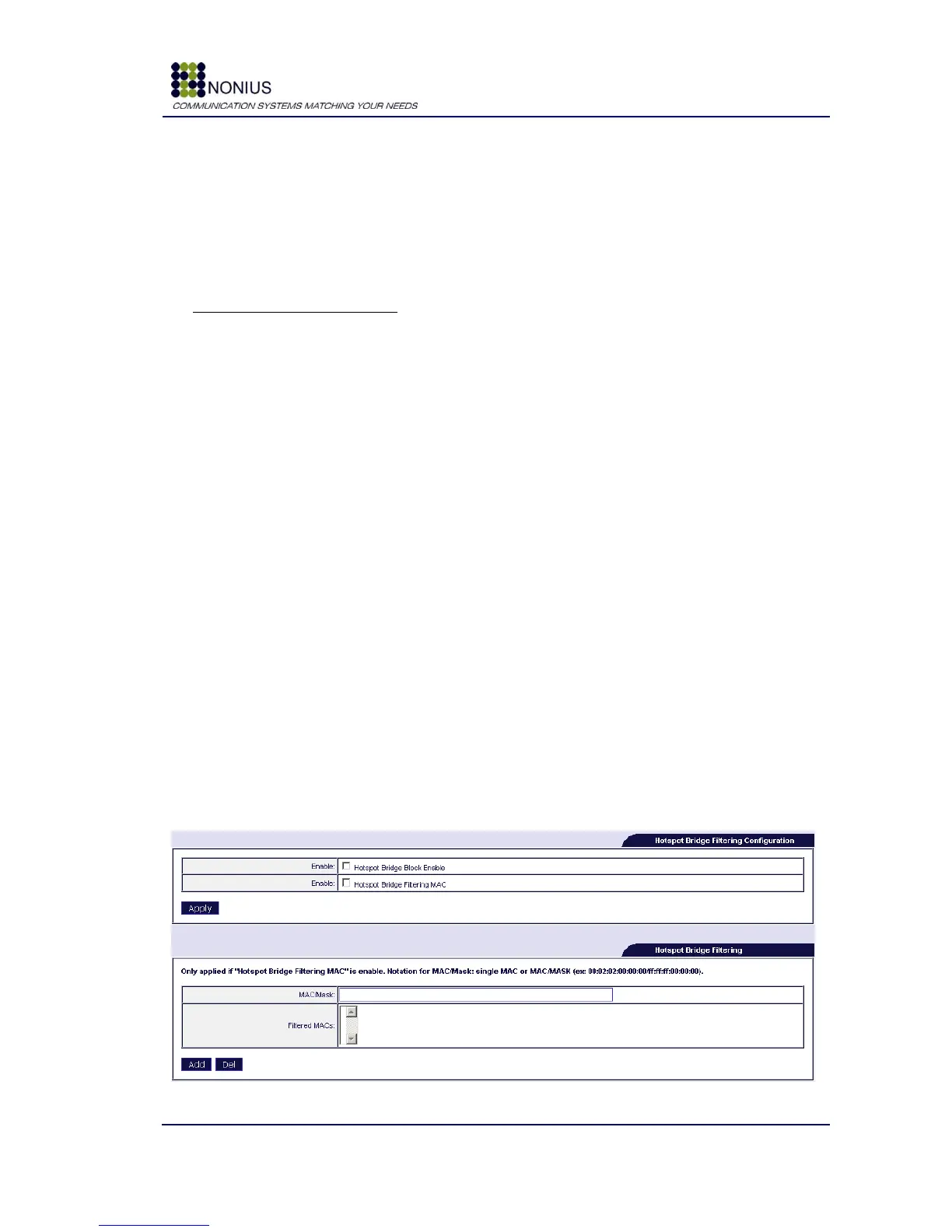
The following forms are used to filter out equipments that may be connected to the WGS5000‟s
hotspot interface but shall not be configured by DHCP.
Figure 17 - Hotspot Bridge Filtering Configuration