OPERATING MANUAL
7-8
21833-3.4
NORMARC 7013
INSTRUMENT LANDING SYSTEM
Corrective maintenance ©1999 Navia Aviation AS
7.4.3 Current data diagnostics
The following sub-sections describes the tests performed by the RMM software for current
data diagnostics. All diagnostic solutions detected are recorded and presented to the opera-
tor. If a diagnostic solution is found to be the result of more than one test, the solution that is
the result of most tests will be listed first.
7.4.3.1 I
2
C read error on any board implies a failure on that board
If a board is reported with “ERROR” status there is probably a fault on this board. “ERROR”
indicates that the RMS does not detect valid I
2
C-bus acknowledge signals from the board
when attempting to read its maintenance data. All boards, except the TX Control board, in the
NM70XX cabinet have an I
2
C-interface to the RMS board.
Note: If all boards are indicated with “ERROR” status, the problem may be a faulty I
2
C inter-
face on the RMS board, or any of the boards may have a “stuck-at” error on the I
2
C bus sig-
nals.
7.4.3.2 Maintenance parameter warnings
7.4.3.2.1 External power supply tests
DIAGNOSTIC ALGORITHM:
If there is a maintenance warning indication on the external power module, there is a problem
with the 27V power supply, the battery chargers or the system is on battery operation.
7.4.3.2.2 Power supply 1 and 2 tests
DIAGNOSTIC ALGORITHM:
1. If there is a maintenance warning indication on power supply 1 and not on power supply 2,
or vice versa, the is a fault on the power supply which has the warning.
2. If there is a maintenance warning on both power supply boards AND not on the external
power module both power supplies are faulty.
7.4.3.2.3 Maintenance warnings without follow-errors
DIAGNOSTIC ALGORITHM:
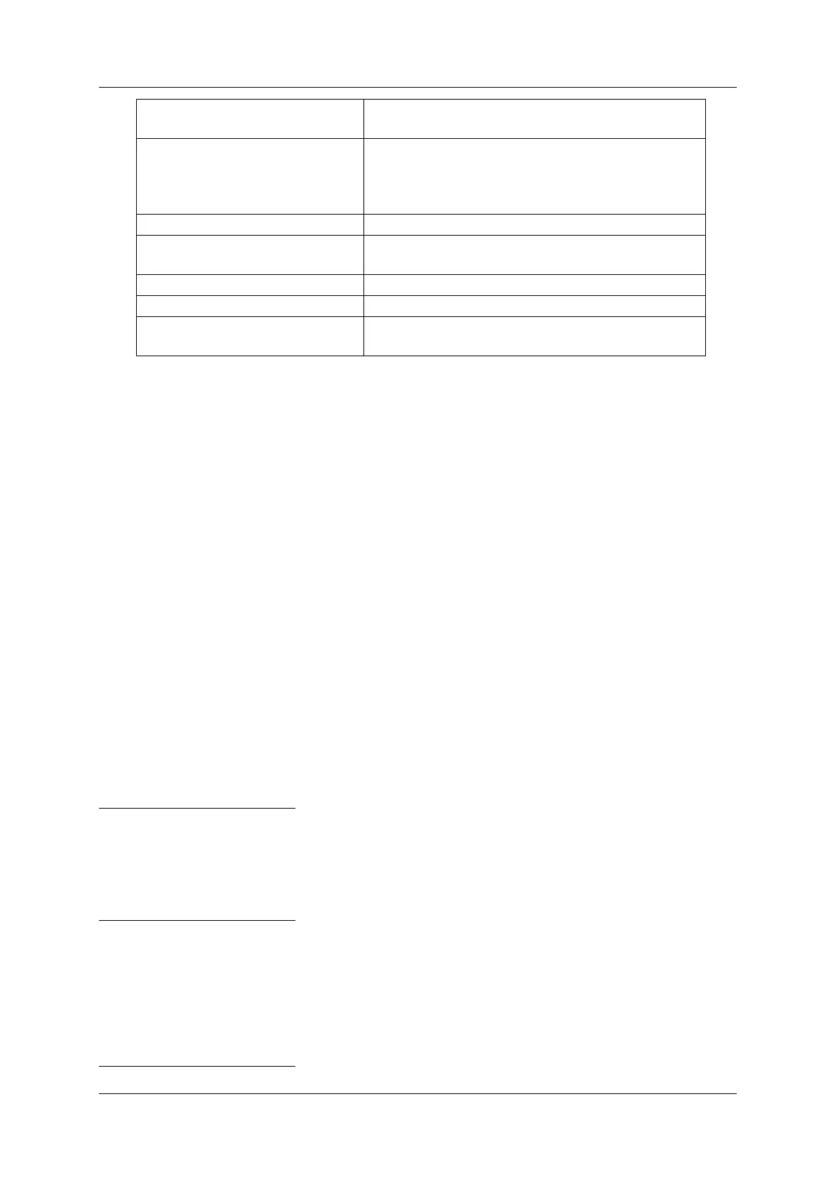
EXTERNAL FACTOR An external factor influencing monitor measure-
ments.
COMMON CABLING Cabling or any part of the system that is common
for the transmitters or monitor system, e.g.
antenna element, cable, distribution- or monitor-
ing networks.
TX CONTROL TX control board (TCA1218) (LRU)
REMOTE CONTROL Remote control unit (RCA1240) (LRU) or its com-
munication link.
ANTENNA SYSTEM Antenna system.
USER INPUT User defined input on CI1210 is in warning state.
UNABLE TO ISOLATE The diagnostic function was unable to determine
a possible faulty module.