©1999 Navia Aviation AS 21833-3.4 Remote Maintenance and Monitoring
OPERATING MANUALNORMARC 7013
INSTRUMENT LANDING SYSTEM
5-45
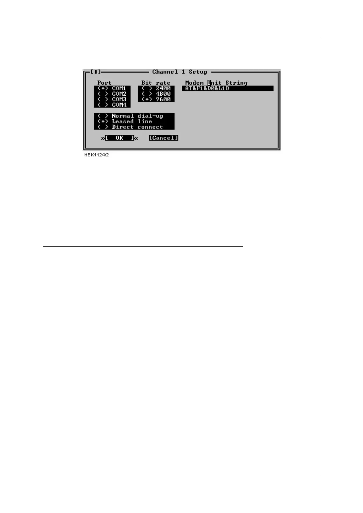
2. Configure the «Channel Setup» for the leased line connection as follows (all ‘0’ letters are
zeroes):
Figure 5-61 RMM channel setup for USR leased-line connections
The modem will be automatically set up for leased when a connection with this channel is
selected by the user.
Users of the DOS version should also select «Use DTR to hangup». The hangup string is
ignored.
5.29 Technical note - Dial up connection SETUP (USRobotics)
USING NM7000 RMM SOFTWARE WITH DIAL UP CONNECTION
Applies to USRobotics Courier Dual Standard V.34+ modems
5.29.1 Definitions
Local modem The modem attached to the PC running
NM7000 RMM software.
Remote modem The modem attached to the NM7000
cabinet.
5.29.2 Configuring the remote modem
1. Set DIP switches on the remote modem.
• Switch 1 must be set to the DTR ALWAYS ON position.
• Switch 4 must be set to the ON position - Do not echo offline commands
• Switch 5 must be set to the AUTO ANSWER ON RING position.
• The remaining switches should be left in their factory default positions.
2. Connecting the modem to the cabinet.
• The remote modem must be connected to Remote Port 2 on the connection interface
board in the ILS cabinet.
3. Configure remote modem init string.
• With a PC running NM7000 RMM software, log in with MASTER access on the Local Port.
• Select «Modem configuration» from the ILS menu.
• Set the Remote port 2 modem configuration as follows (All ‘0’ letters are zeroes.):