©1999 Navia Aviation AS 21833-3.4 Monitor and Maintenance Parameters
OPERATING MANUALNORMARC 7013
INSTRUMENT LANDING SYSTEM
A-1
PART IV APPENDIX
A Monitor and Maintenance Parameters
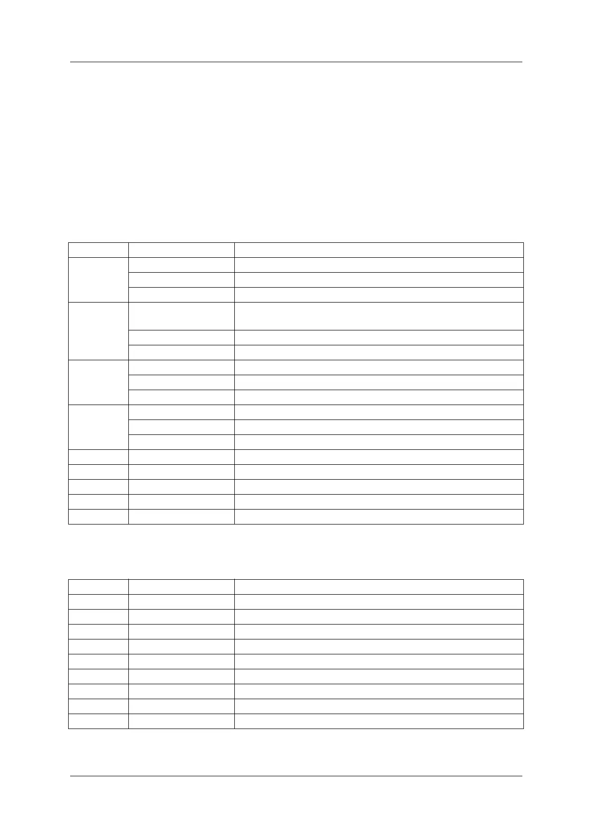
A.1 Monitor Alarm Parameters
These are ILS parameters measured by the monitors. An alarm on any of these parameters
will cause change-over/shut-down.
Table A-1 Monitor Alarm Parameters - Monitor Window 1.
Table A-2 Monitor Alarm Parameters - Monitor Window 2.
Channel Parameter Description
CL DDM Course Line - Difference in depth of modulation
SDM Course Line - Sum of depth of modulation
RF Course Line - RF level
DS DDM Displacement Sensitivity - Difference in depth of modula-
tion
SDM Displacement Sensitivity - Sum of depth of modulation
RF Displacement Sensitivity - RF level
NF DDM Near Field - Difference in depth of modulation
SDM Near Field - Sum of depth of modulation
RF Near Field - RF level
CLR DDM Clearance - Difference in depth of modulation
SDM Clearance - Sum of depth of modulation
RF Clearance - RF level
- DF Difference Frequency
- CL IDENT IDENT signal from CL monitor (LLZ only)
- CLR IDENT IDENT signal from CLR monitor (LLZ only)
- Self test Logical OR of monitor self test signals
- DC LOOP Logical OR of DC-LOOP signals (LLZ only)
Channel Parameter Description
- TEST: DDM Monitor self test signal
- TEST: SDM Monitor self test signal
- TEST: RF Monitor self test signal
- CL ID MOD IDENT signal modulation on CL monitor (LLZ only)
- CLR ID MOD IDENT signal modulation on CLR monitor (LLZ only)
- DC LOOP 0 DC-LOOP for antenna element group 0 (LLZ only)
- DC LOOP 1 DC-LOOP for antenna element group 1 (LLZ only)
- DC LOOP 2 DC-LOOP for antenna element group 2 (LLZ only)
- DC LOOP 3 DC-LOOP for antenna element group 3 (LLZ only)