OPERATING MANUAL
A-4
21833-3.4
NORMARC 7013
INSTRUMENT LANDING SYSTEM
Monitor and Maintenance Parameters ©1999 Navia Aviation AS
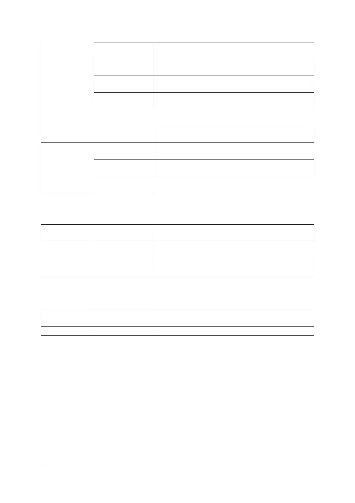
Table A-5 DC Supplies Maintenance Parameters.
Table A-6 User Defined Analog Inputs Maintenance Parameters.
Table A-7 User Defined Logical Inputs/Outputs Maintenance Parameters.
TX1 COURSE
I150
Measured value of current through TX1 COURSE
150Hz amplifier
TX1 COURSE I90 Measured value of current through TX1 COURSE
90Hz amplifier
TX2 CLR I150 Measured value of current through TX2 CLR 150Hz
amplifier
TX2 CLR I90 Measured value of current through TX2 CLR 90Hz
amplifier
TX2 COURSE
I150
Measured value of current through TX2 COURSE
150Hz amplifier
TX2 COURSE I90 Measured value of current through TX2 COURSE
90Hz amplifier
CI1210 CHARGER STA-
TUS
Charger Voltage OK / not OK
BATT CURRENT Measured value of battery current (negative if charg-
ing)
POWER CUR-
RENT
Measured value of total system current consumption
Originates from
module
Parameter Description
CI1210 Temp in Inside temperature (if installed)
Temp out Outside temperature (if installed)
AC voltage Mains voltage (if installed)
User defined 3 user defined analog inputs
Originates from
module
Parameter Description
CI1210 User defined 8 user defined logical inputs/outputs