OPERATING MANUAL
5-24
21833-3.4
NORMARC 7013
INSTRUMENT LANDING SYSTEM
Remote Maintenance and Monitoring ©1999 Navia Aviation AS
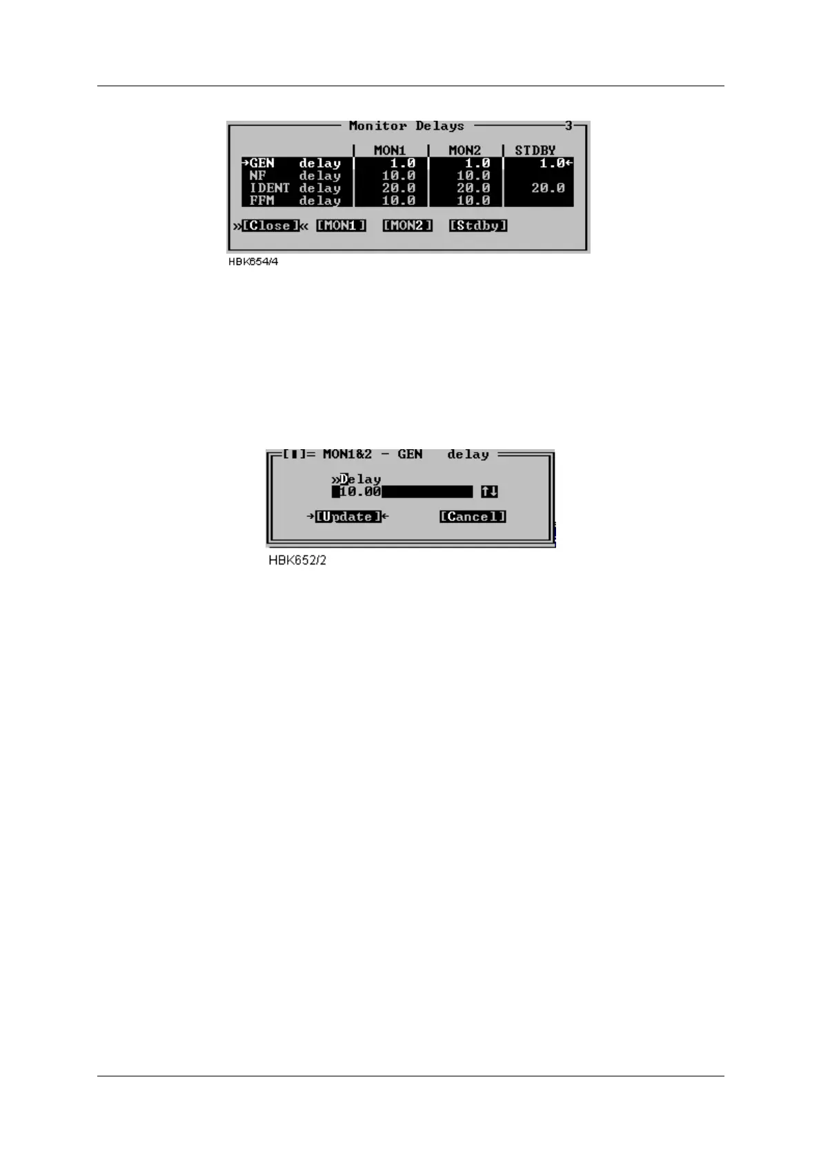
Figure 5-25 Monitor delays window
A standby column will be shown if the system is equipped with a standby monitor. The resolu-
tion of the delay parameters is 1/10 second.
Once the “Mon 1 and 2” or the “Stdby” button has be pressed an input dialog like the one show
below is opened. Enter the desired delay in the field, or use the up and down arrows to incre-
ment/decrement the current value. When the “Update” button is selected, the ILS will be
updated.
Figure 5-26 Delay input dialog
Valid input range in this window is 0.4 to 102.3 seconds. The total changeover-shutdown
delay will be two times this value. See Appendix B for recommended values.
5.8.4 Limits Maintenance monitor
When the ILS|Monitor settings|Analog maintenance limits or Digital maintenance limits menu
item is selected a window showing the currently configured analog/digital maintenance moni-
tor warning limits is displayed. Windows with sample data is displayed below. The board name
is shown idented to the left. The maintenance parameters is show after each board name.
For analog parameters the “Low” and “High” columns shows the low and high warning limits.
For digital parameters a single column show the “normal state” for the parameter. If the
parameter state is not equal this state a maintenance warning will be generated by the ILS
RMM software. If no warning is wanted for a parameter the columns will display “OFF”.
See Appendix B for factory default settings.