OPERATING MANUAL
5-16
21833-3.4
NORMARC 7013
INSTRUMENT LANDING SYSTEM
Remote Maintenance and Monitoring ©1999 Navia Aviation AS
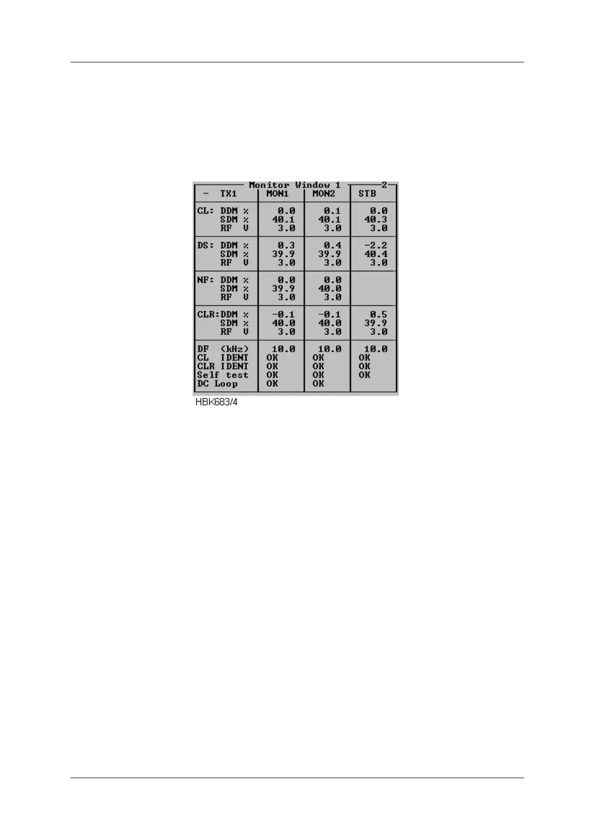
To display the parameters shown in the window below select the ILS|Measurements|Monitor
Window 1 menu item. This window displays the standard monitor parameters (DDM, SDM
and RF-level) for each of the monitor channels (Course line, Displacement Sensitivity, Near
field and Clearance Transmitter (2-freq. systems)). In addition, Difference Frequency (2-
freq.systems), DC-loop and Ident information are displayed. The result of the continuous mon-
itor self test is also shown.
Figure 5-12 Monitor window
The DC loop status shown in this window will be OK if all the DC loop readings are within the
warning limits, else ERROR is displayed (DC loop readings for each loop is displayed in Mon-
itor window II).
5.7.3 Additional monitor parameters window
Selecting ILS|Measurements|Monitor 2 brings up the following window. This window shows
secondary monitor parameters.
Due to the nature of the monitor self test signals, the values will toggle between alarm and
normal. If one of these erroneous test signals fails to generate alarm, a self test error will be in
Monitor Window 1. The CL/CLR MORSE parameters shows the modulation level of the ident
signal. No activity on this signal for the time period specified in the ident delay setting, will
result in an IDENT warning in Monitor Window 1.
Depending on the antenna system installed, up to 4 DC-loops can be active. The DC LOOP
parameter in Monitor Window 1 shows accumulated status of the 4 DC-loops.