©1999 Navia Aviation AS 21833-3.4 SYSTEM DESCRIPTION
OPERATING MANUALNORMARC 7013
INSTRUMENT LANDING SYSTEM
1-1
PART I DESCRIPTION
1 SYSTEM DESCRIPTION
1.1 System Overview
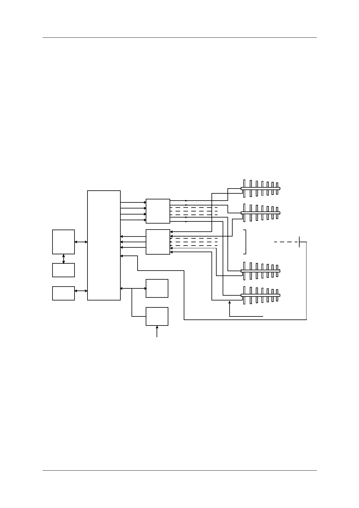
The NM 7000-series Localizers comprises the following units or sub-systems:
• Localizer Cabinet
• Power Supply
• Remote Control
• RMM System (Optional)
Figure 1-1 LLZ block diagram
The Antenna System with distribution and monitor networks are described in a separate man-
ual.
The Localizer cabinet comprises:
• Dual transmitter/modulators
• Dual monitors in "2 out of 2" voting
• Priority and change-over system with local control panel
• Remote monitoring system with local display and RS-232 ports for local and remote PC
connections.
The Power supply is a separate, wall mounted unit. Back-up batteries are float charged, and
MAINS INPUT
TION NETW.
DISTRIBU-
SYSTEM
RMM
PANEL
SLAVE
SUPPLY
POWER
BATTERY
24V
CONTROL
UNIT
REMOTE
MONITOR
MODULATOR
TRANSMITTER
CLR*
NF
DS
CL
MONITOR
NETWORK
SBO CLR*
CSB CLR*
SBO CL
CSB CL
ANTENNA
TRANSMITTER
ILS LOCALIZER
OUTPUT PROBE
MONITOR
ARRAY
LOCALIZER ANTENNA
RUNWAY CL.
HBK204-1
AND
I and II
I and II
ILS Localizer
220V/110V AC
* CLR SIGNALS N/A on single-frequency equipment