OPERATING MANUAL
5-28
21833-3.4
NORMARC 7013
INSTRUMENT LANDING SYSTEM
Remote Maintenance and Monitoring ©1999 Navia Aviation AS
The following definitions can be made for the digital user parameters: Name, input or output
selection, whether the value shall be inverted or not, and warning state of the parameter
(TRUE / FALSE / NONE).
To change the setting for a I/O parameter, select the parameter on the list and press the
“Change” button. This brings up the dialog shown below.
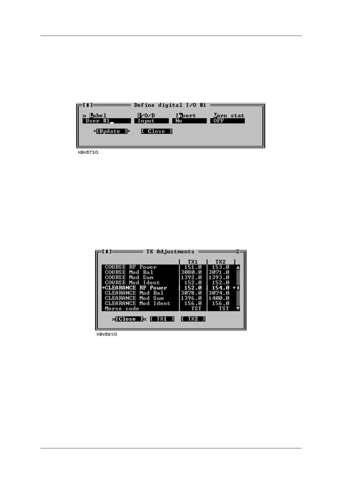
Figure 5-35 Digital user parameters settings dialog
For the counter parameters; the “Change” button opens a dialog where the label text can be
modified.
5.9 TX settings
5.9.1 TX Adjustments
Selecting the ILS|TX settings|TX adjustments menu item opens the window shown below.
Figure 5-36 TX adjustments window
The following TX parameters can be changed for Course and Clearance (2-freq. systems) for
transmitter 1 and 2:
• 90Hz & 150Hz modulation balance (DDM),
• 90Hz & 150Hz modulation sum (SDM),
• RF power
• Ident modulation depth
• In addition, the runway Morse code identification (2-4 letters) is entered here.
To change TX adjustment values click the TX1 or TX2 buttons. A dialog similar to the one
below will be opened. To change the parameter value you have the following options:
• Click on the up and down arrows to increment/decrement the value. The ILS will automati-