©1999 Navia Aviation AS 21833-3.4 Remote Maintenance and Monitoring
OPERATING MANUALNORMARC 7013
INSTRUMENT LANDING SYSTEM
5-27
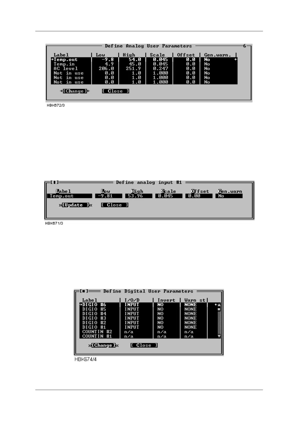
window shows the current settings for the analog user parameters.
Figure 5-32 Analog user parameters definitions
The following definitions can be made for the analog user parameters: Name, lower and upper
warning limits, and scale and offset constants for conversion to engineering units. There is
also a field for enabling/disabling generation of a maintenance warning.
To change the settings for a parameter, select the parameter on the list and press the
“Change” button. This brings up the dialog shown below.
Figure 5-33 Analog user parameter settings dialog
5.8.7 Digital user parameters
Selecting ILS|Monitor settings|Digital user parameters opens the window shown below. This
window shows the current settings for the digital user parameters. There are six parameters
which operate as digital input or output, and two parameters which count number of positive
transitions on the corresponding digital inputs. The counter will count from 0 to 99, and be
automatically reset to 0.
Figure 5-34 Digital user parameters definitions