OPERATING MANUAL
5-30
21833-3.4
NORMARC 7013
INSTRUMENT LANDING SYSTEM
Remote Maintenance and Monitoring ©1999 Navia Aviation AS
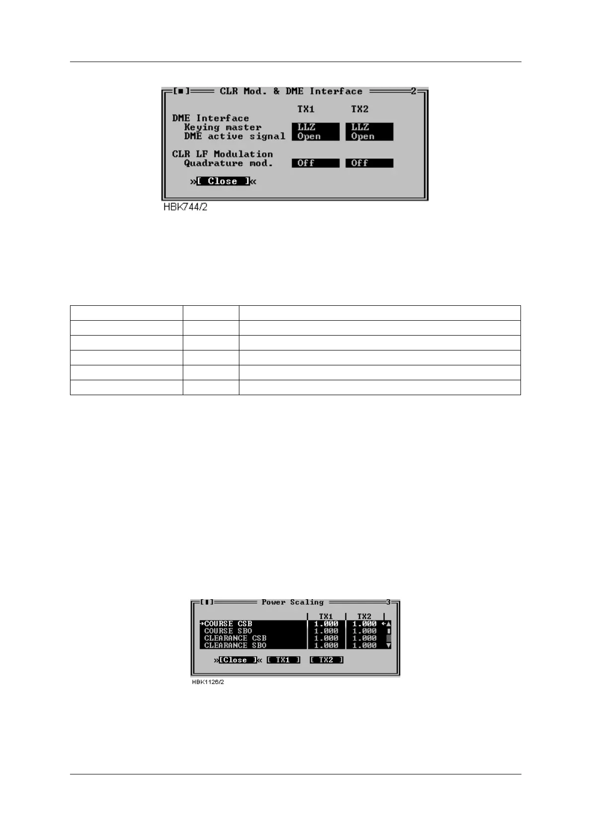
Figure 5-39 CLR mod. and DME settings dialog
The fields in this window specifies the operation of the DME interface (LLZ only) and quadra-
ture modulation of the CLR LF signal (2-freq. systems only).
The following table describes the each selection.
Table 5-11 CLR modulation and DME settings.
5.10 Power scaling
NOTE
The scaling values in this window should only be changed on racks with the first ver-
sion of the PA module (LPA1230A/GPA1231A/GPA1232A version 1). On newer PA mod-
ules, the power reading is pre-adjusted, and the scaling value should be set to 1.0.
Selecting ILS|TX Settings|Power scaling when connected to an ILS with RMS software ver-
sion 10, or later, will bring up the window below.
Figure 5-40 Power scaling settings
The scaling values will normally be in the range 0.5-2.0.
The values in this window can be used to adjust the power measurements done on the trans-
mitters. The measurement values are displayed in the maintenance windows for the transmit-
Keying master LLZ LLZ is the keying master
DME DME is the keying master
DME active signal OPEN Open circuit indicates active DME (enables colocation)
CLOSED Closed circuit indicates active DME (enables colocation)
Quadrature mod. OFF Do not quadrature modulate the clearance LF signal.
ON Enable quadrature modulation of the clearance LF signal.