©1999 Navia Aviation AS 21833-3.4 Remote Maintenance and Monitoring
OPERATING MANUALNORMARC 7013
INSTRUMENT LANDING SYSTEM
5-17
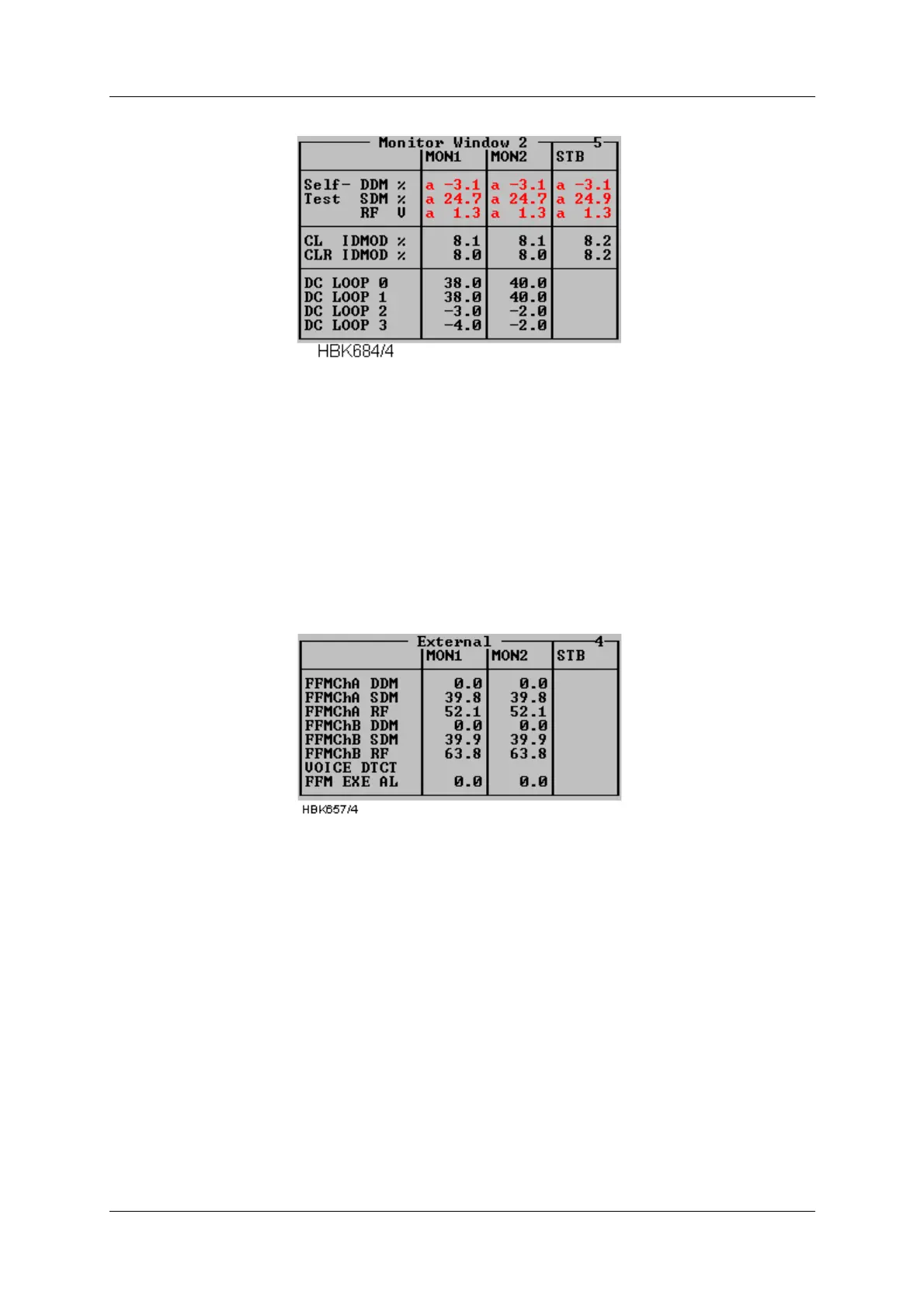
Figure 5-13 Additional monitor parameters window
5.7.4 External parameters window
Selecting ILS|Measurements|External brings up the following window. This window shows the
measurements on the external channels. The NM 70xx can provide executive monitoring of
signals from external equipment, defined by the user (option).
For external channels that are not used, no measurement field will be shown (e.g. the standby
measurement field will be shown (e.g. the standby measurements in Figure 5-14)
Figure 5-14 External parameters window
5.7.5 Maintenance monitor window
Selecting ILS|Measurements|Maintenance brings up the window shown below. The mainte-
nance warning parameters are displayed in groups corresponding to the modules on which
they are measured. A separate group consists of the main power supplies and current mea-
surements. In this way, the origin of a maintenance warning can easily be deduced.
If one maintenance parameter on a module is in warning status, the module to which it
belongs is given the same status. Therefore, it can be easily determined the maintenance
warning status of the system by looking at the top window (Figure 5-15) only.
The following table shows the defined status codes.