OPERATING MANUAL
6-6
21833-3.4
NORMARC 7013
INSTRUMENT LANDING SYSTEM
Periodic maintenance CAT I and II ©1999 Navia Aviation AS
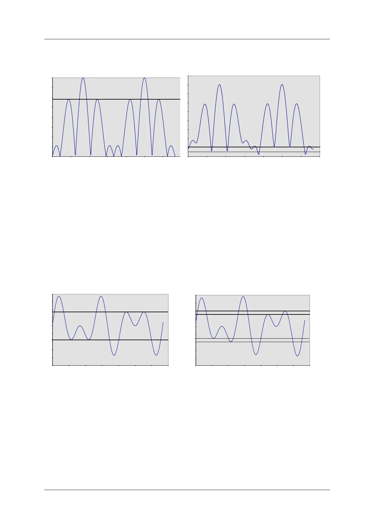
Figure 6-2 RF phase check
6.4.3.4 CSB waveform check. LF phase
Switch on Course Tx1.
• Connect the Oscilloscope to CSB test connector on Course Tx1 Section via 50 ohm test
cable.
• Set the Oscilloscope input mode to DC.
Look for the intermediate peaks of the CSB demodulated waveform. Check that the waveform
resembles the graph below (left). The intermediate waveform peaks shall have the same max-
imum and minimum level, indicating 90/150 Hz zero phase start.
Figure 6-3 LF phase check
6.4.3.5 DDM and SDM check.
Switch on Tx1.
• Connect the Field Test Set to the CSB Cou test connector on the Change Over Section
through a 20 or 30 dB attenuator.
• Use a double shielded 50 ohm coaxial test cable. On the Field Test Set read DDM. The
nominal reading should be 0.0% DDM.
• On the Field Test Set read SDM. The nominal reading should be 40.0%, or the same as the
previous reading/ commissioned value.
6.4.3.6 Ident modulation check.
DEMODULATED SBO-SIGNAL: NORMAL DEMODULATED SBO-SIGNAL: 5° RF-PHASE ER-
ROR
DEMODULATED CSB: NORMAL DEMODULATED CSB: 10° LF PHASE ERROR