OPERATING MANUAL
B-4
21833-3.4
NORMARC 7013
INSTRUMENT LANDING SYSTEM
Factory default configuration settings ©1999 Navia Aviation AS
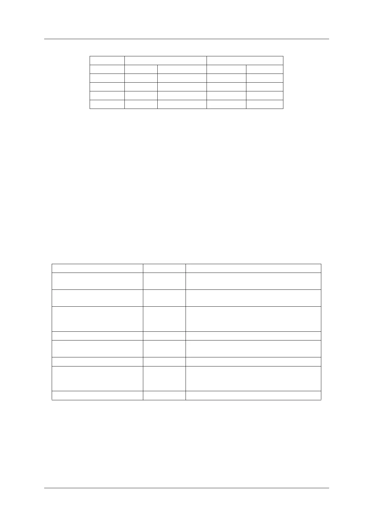
Table B-4 Factory default delay values.
B.5 Maintenance parameter configuration
This following sub-sections describes the maintenance measurements collected by the RMS
for diagnostic purposes. Default warning limits is also defined for each measurement type.
The warning limit for digital measurement point, are set to the “normal” state of the measure-
ment point. For example, for a measurement point that is normally “HIGH”, the warning limit is
set to “HIGH”.
For analog measurement points the limits are specified as “low limit”/”high limit”.
See chapter 5.8.4 in the Operating Manual for information on using the RMM software to set
these limits.
B.6 Oscillator 1 and 2 (OS 1221)
LLZ GP
Channel Cat I Cat II/III Cat I Cat II/III
GEN 5 s 1 s 3 s 1 s
NF 20 s 20 s 20 s 20 s
IDENT 20 s 20 s N/A N/A
FFM 60 s 60 s 60 s 60 s
Measurement Warn. limit. Description
COU OUTPUT LEVEL HIGH Detects low output level from the board.
May cause low radiated power.
COU TUNEVOLT HIGH Voltage Controlled Oscillator parameter
drift.
COU SYNTH LOCK HIGH The phase locked loop has been out of
lock. (May be reset by turning the TX off/
on.)
COU LOCK DETECT HIGH Output frequency is unstable.
CLR OUTPUT LEVEL HIGH Detects low output level from the board.
May cause low radiated power.
CLR TUNEVOLT OK HIGH Voltage controlled oscillator parameter drift.
CLR SYNTH LOCK HIGH The phase locked loop has been out of
lock. (May be reset by turning the TX off/
on.)
CLR LOCK DETECT HIGH Output frequency is stable/not stable.