©1999 Navia Aviation AS 21833-3.4 Corrective maintenance
OPERATING MANUALNORMARC 7013
INSTRUMENT LANDING SYSTEM
7-11
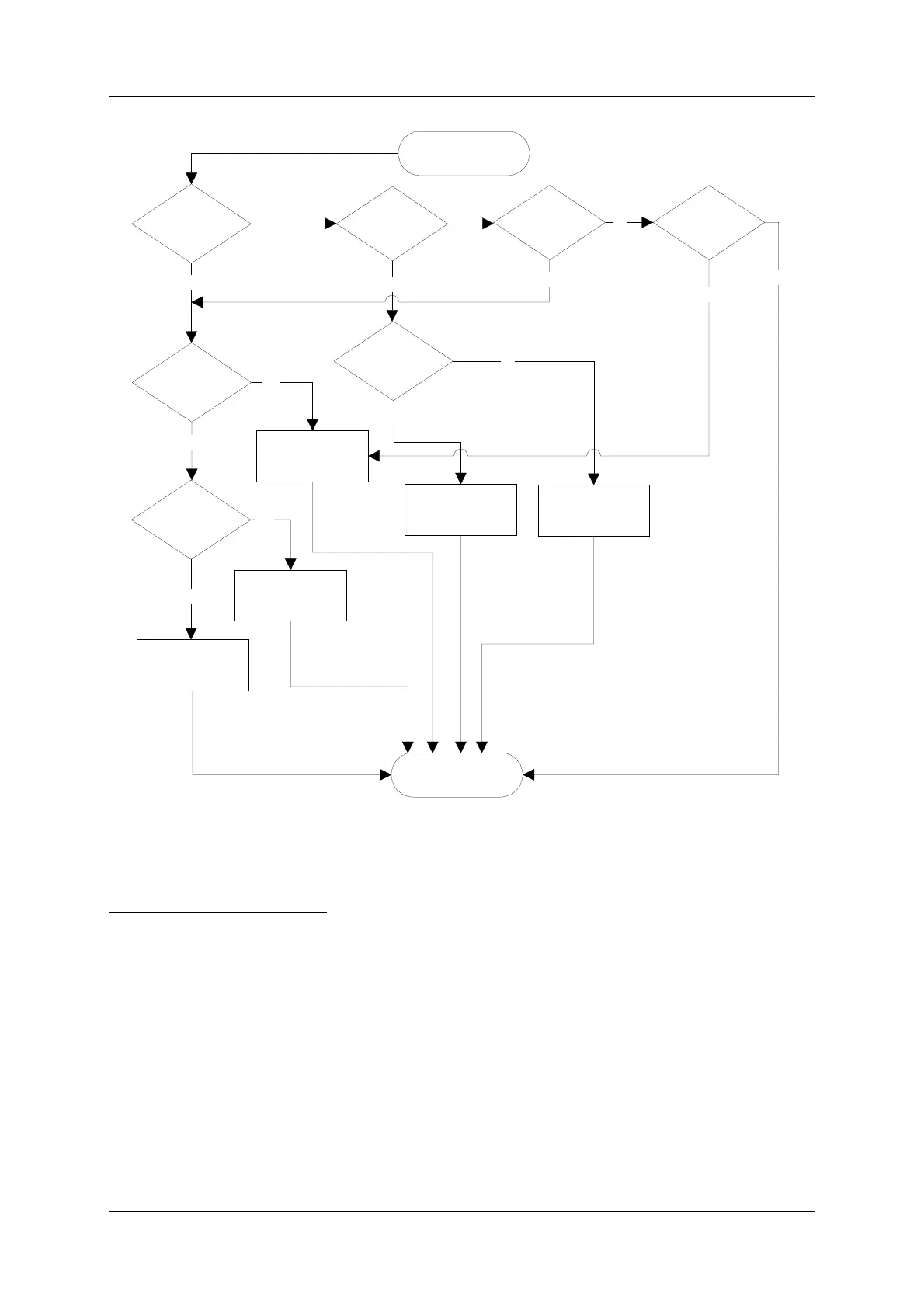
Figure 7-1 Flow diagram for Monitor warning tests.
7.4.3.6 Monitor disagree
DIAGNOSTIC ALGORITHM:
If one monitor indicates delayed warning, raw alarm or alarm on any parameter and the other
monitor does not, then the monitor which indicates the delayed warning, raw alarm or alarm is
probably faulty.
7.4.4 Alarm event diagnostics
7.4.4.1 Changeover without shutdown
The flow diagram in Figure 7-2 describes the algorithm used to diagnosing a changeover
alarm that is not followed by a shutdown alarm. The RMM software uses the maximum config-
ured monitor alarm delay to determine whether a changeover alarm is followed by a shut-
down. If no shutdown alarm event occurred within the maximum configured alarm delay after
the changeover alarm event this algorithm will be used.
Common cabling is
faulty
CL or DS
warning on both
monitors?
NF warning on
both monitors?
No
CLR warning
on both
monitors?
No
Warning on
active OS?
Warning on
active LF?
Warning on NF
RF on one or
both mon.?
Yes
Yes
Yes
"External factor" is
reported as faulty.
No
Active OS is faulty
Active LF is faulty
Monitor warning
tests done.
Active course or
clearance PA is faulty
Yes
Yes
DF warning on
both monitors?
No
Yes
No
Start monitor
warning tests.
Yes
No
No