©1999 Navia Aviation AS 21833-3.4 Factory default configuration settings
OPERATING MANUALNORMARC 7013
INSTRUMENT LANDING SYSTEM
B-3
large enough to periodically produce a CL or CLR IDENT measurement that is greater than
this low limit to reset the IDENT delay counter. All measurements that is greater than this min-
imum value should be accepted, the upper warning limit is therefore set to a large value (20 is
the recommended value).
If executive changeover/shutdown is desired on alarms on the CL or CLR IDENT parameters,
the warning limits recommended above should be used, instead of OFF, on the alarm limits.
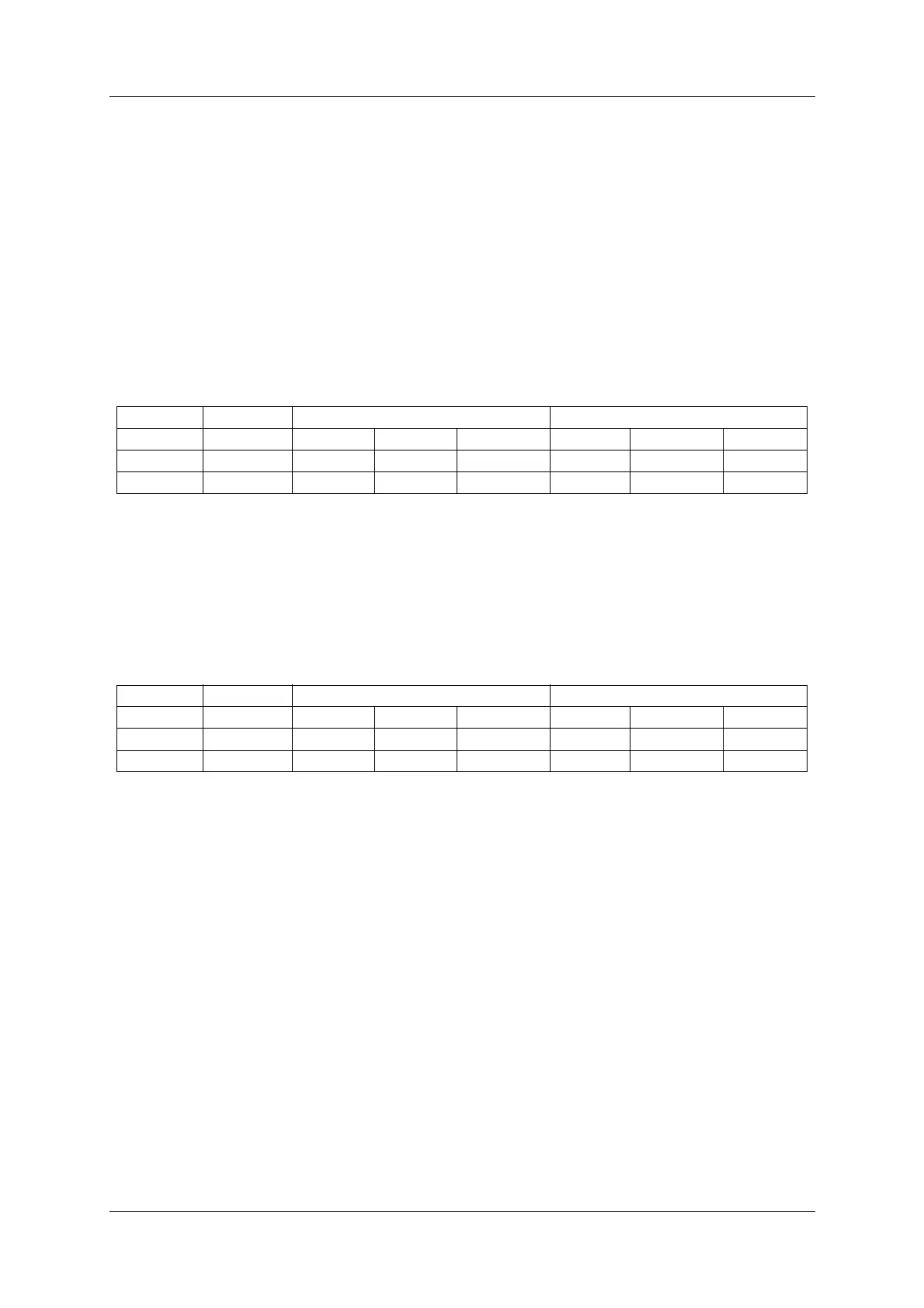
B.2 Cat II monitor LIMIT configuration
For Cat II equipment the monitor limits are configured as for Cat I (see table 1), with the
exceptions shown in Table B-2. (Only the LLZ limits are different.)
Table B-2 Alarm and warning limits for Cat II equipment.
B.3 Cat III monitor LIMIT configuration
For Cat III equipment the monitor limits are configured as for Cat I (see table 1), with the
exceptions shown in Table B-3. (Only the LLZ limits are different.)
Table B-3 Alarm and warning limits for Cat III equipment.
B.4 Executive Monitor delay configuration
The factory default delay configuration for Cat I and II/III (values compliant with ICAO Annex
10) are shown in Factory default delay values..
Note that Annex 10 specifies the total changeover + shutdown delay after an alarm. The delay
values used in the NORMARC 7000 RMM software are the time delay between the detection
of an alarm and the resulting changeover or shutdown. When a changeover takes place the
delay counters are reset. The values entered in the RMM software are therefore set to the
Annex 10 value divided by two.
The NF delay is used for alarms on the NF DDM, SDM and RF parameters. The IDENT delay
is used on the CL/CLR IDENT, MORSE and VOICE parameters. The FFM delay is used on all
FFM parameters including FFM EXE AL. The GEN delay is used on all remaining parameters.
See chapter 5.8.3 in the Operating Manual for information on delay configuration using the
RMM software.
LLZ GP
Channel Signal Nom Ala H/L Wa H/L Nom Ala Warn
CL DDM 0.0 % -1.1/1.1 75 % 0.0 % -3.73/3.73 75 %
NF DDM 0.0 % -1.1/1.1 75 % 0.0 % -5.25/5.25 75 %
LLZ GP
Channel Signal Nom Ala H/L Wa H/L Nom Ala Warn
CL DDM 0.0 % -0.9/0.9 75 % 0.0 % -3.73/3.73 75 %
NF DDM 0.0 % -0.9/0.9 75 % 0.0 % -5.25/5.25 75 %