©1999 Navia Aviation AS 21833-3.4 Periodic maintenance CAT I and II
OPERATING MANUALNORMARC 7013
INSTRUMENT LANDING SYSTEM
6-5
(Each modulator develops it's own waveform shape due to spreads in insertion phases).
The dynamic maximum point should be approximately -4 volt.
6.4.3.2 SBO waveform checks.
Switch on Course Tx1.
• Connect the Oscilloscope to SBO test connector on Course Tx1 Section via 50 ohm test
cable.
• Set Oscilloscope input mode to DC.
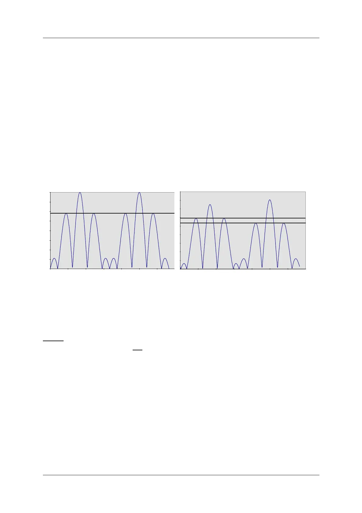
• Check that the waveform resembles the graph below, left.
For best signal resolution on the scope, it is advisable to set the oscilloscope in double sweep
rate and FREE RUN trigger mode ("kissing pattern" mode). The two halves of the 30 Hz wave-
form will then overlap and look like one waveform when perfect power balance is achieved.
Figure 6-1 SBO Waveforms
6.4.3.3 RF Phase
• Connect the Oscilloscope to SBO test connector on Course Tx1 Section via 50 ohm test
cable.
NOTE:
Set the scope's input mode to DC.
Set the oscilloscope in normal trigger mode such that the waveform below can be observed.
The observed waveform should resemble the NORMAL graph on the left.
DEMODULATED SBO: NORMAL IMBALANCE (150Hz<90Hz)
DEMODULATED SBO: 1dB POWER