©1999 Navia Aviation AS 21833-3.4 Remote Maintenance and Monitoring
OPERATING MANUALNORMARC 7013
INSTRUMENT LANDING SYSTEM
5-37
Figure 5-48 User configuration dialog
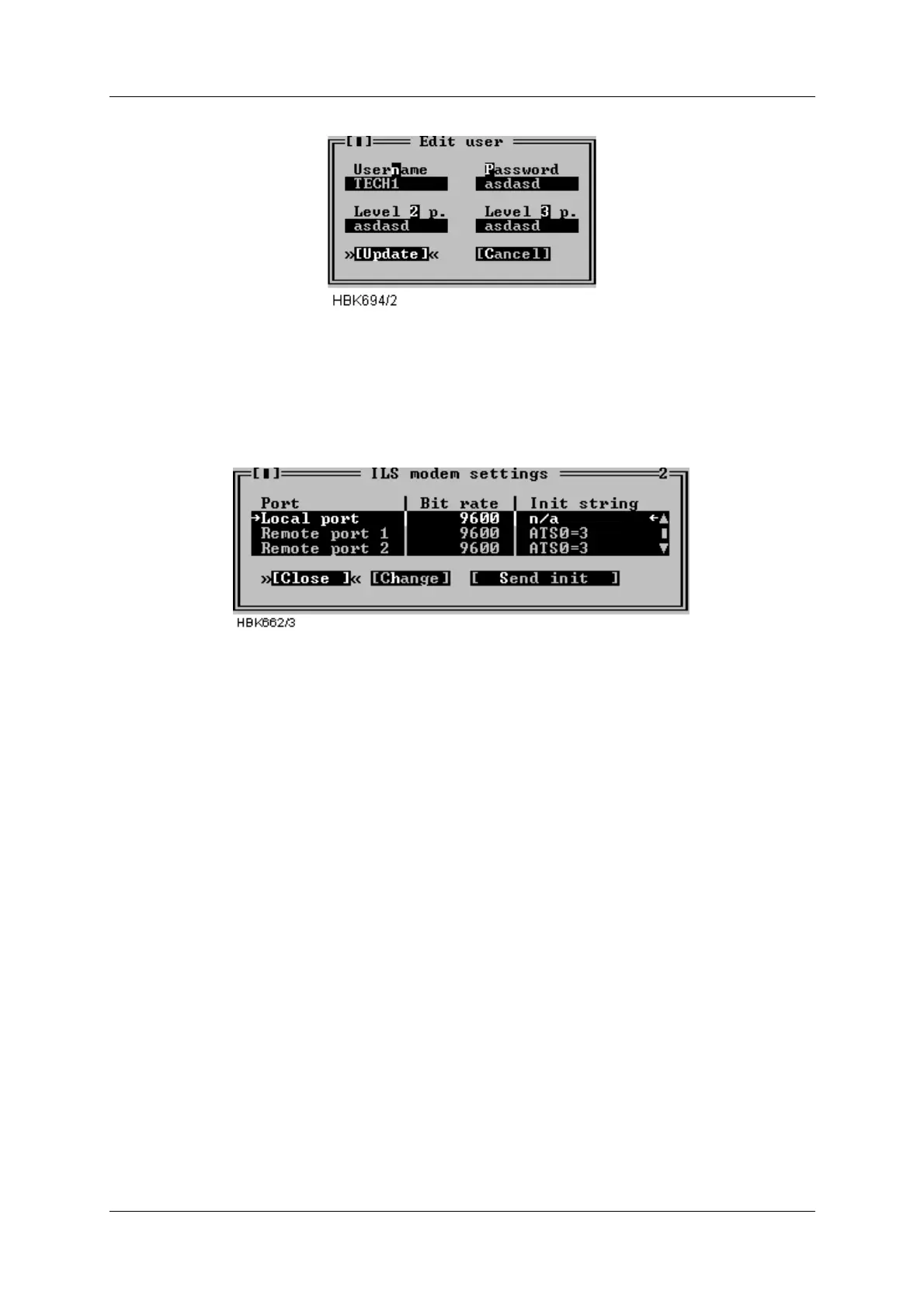
5.18 ILS Modem settings
With access level 3 you have access to change ILS modem bit rate and initiation strings and
make the ILS initiate the modems. Selecting ILS|Modem configuration brings up the window
shown below.
Figure 5-49 ILS Modem settings window.
The window displays the currently configured bit rates and init strings. Pressing the Change
button brings up a dialog where you can change the bit rate and/or the init string for the
selected port. Note that it is no init string for the local port, since a modem is not supported for
this port.
Pressing the Send init button starts modem initiation at the selected port. When the ILS is
done initiating a dialog showing the result of the modem initiation will appear.
If the init-string is left blank or the word «default» is written, the ILS will use a default init-string
that shall work on standard Hayes compatible modems under normal conditions.
Please consult the modem manual for further information about modem commands and initial-
isation.
5.19 Upload configuration to ILS
Several boards in the NORMARC 7000 cabinet store settings or operational parameters in
internal EEPROM. Whenever a new board is inserted in a cabinet, these parameters need to
configured. This can be done by “uploading” the parameter values to the cabinet with the use
of the “ILS | Configuration options | Upload configuration to ILS” menu item. When this menu
item is chosen, a window for selecting a previously stored “CFG” file (see section 5.20) is dis-
played.
Once the user has selected the file containing the desired configuration parameters, the win-
dow shown in Figure 5-50 is opened. This window lists boards for which the configuration may