OPERATING MANUAL
7-12
21833-3.4
NORMARC 7013
INSTRUMENT LANDING SYSTEM
Corrective maintenance ©1999 Navia Aviation AS
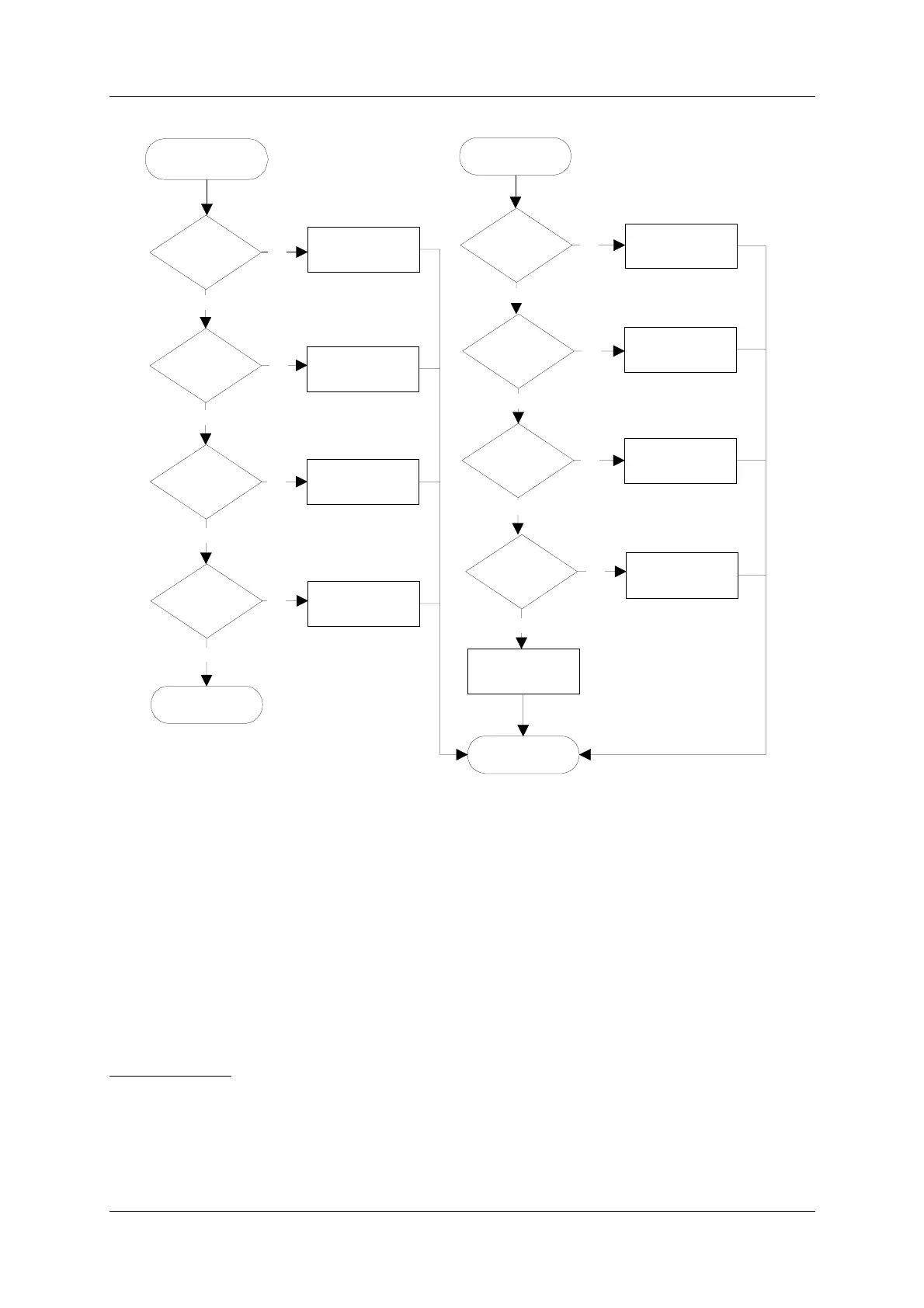
Figure 7-2 Flow diagram for diagnosing a changeover-only alarm.
7.4.4.2 Changeover with subsequent shutdown
A changeover alarm event that is followed by a shutdown alarm event within the maximum
configured monitor delay will be diagnosed as described in this section. The algorithm used
depends on the voting configuration.
7.4.4.3 Algorithm for systems with 2/2 voting
Figure 7-3 shows the flow diagram for diagnosing changeover/shutdown situations on sys-
tems with 2/2 voting.
DESCRIPTION:
The algorithm is based on the fact that a fault (in a 2/2 voting system) which causes a com-
plete shutdown, must be some point that is common for the transmitter section and the moni-
Start changeover
diagnostics
Changeover
diagnose done
Maint warn on
main OS?
Maint warn on
main LF?
Maint warn on
main COU TX?
Maint warn on
main CLR TX?
CL or DS
alarm?
NF alarm?
CLR alarm?
DF alarm?
No
No
No
Main OS is faulty
Main LF is faulty
Main COU TX is
faulty
Main CLR TX is
faulty
Main COU TX is
faulty
External obstruction
is blocking signal
Main CLR TX is
faulty
Main OS is faulty
No maintenance
warnings
No maintenance
warnings
Unable to diagnose
fault
No
No
No
No
Yes
Yes
Yes
Yes
Yes
Yes
Yes
Yes
No