©1999 Navia Aviation AS 21833-3.4 Maintenance Procedures
OPERATING MANUALNORMARC 7013
INSTRUMENT LANDING SYSTEM
C-23
7. Place the function selector switch to LOCALIZER or GLIDE SLOPE, as appropriate, and
read the 90 Hz and 150 Hz modulation percentages on the PERCENT MODULATION indi-
cator.
8. Record the percentages on FAA Form 6750-32, and determine if they are in tolerance.
9. At two-frequency facilities, complete the steps above for the clearance transmitter on a dif-
ferent FAA Form 6750-32. (Test cable connected to CLR CSB test connector.)
10.Restore the equipment to normal.
5-48 thru 5.51 Reserved.
5.52 Not recommended for Navia Aviaion ILS.
5.53 Not recommended for Navia Aviaion ILS.
5-55 thru 5-60 Reserved.
5-61 Not applicable.
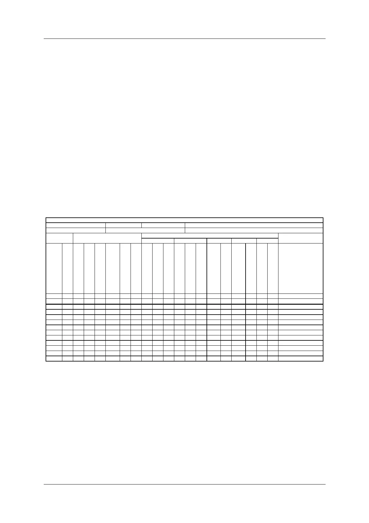
Table C-1 Localizer Monitor Reference Data
Technical Performance Record Localizer Monitor Reference Data
IDENTIFICATION LOCATION FROM SUPERVISORS SIGNATURE
EQUIPMENT NUMBER EQUIPMENT TYPE REFERENCE FLIGHT INSPECTION DATE
Normal Alarms
Wide Narrow 90 Hz 150 Hz Rf level
DATE
YEAR
TIME
COU CSB voltage (mV dc
COU CSB power (W)
COU SBO voltage (mV dc
COU CSB DDM
(Carrier feedline)
Width monitor DDM(DS)
Course monitor DDM (CL)
COU SBO voltage (mV dc)
SBO attenuator value (dB)
Width monitor DDM (DS)
COU SBO voltage (mV dc)
SBO attenuator value (dB)
Width monitor DDM (DS)
COU CSB DDM
(Carrier feedline)
Course monitor DDM (CL)
COU CSB DDM
(Carrier feedline)
Course monitor DDM (CL)
COU CSB voltage (mV dc
COU CSB power (W)
Remarks
Reference
Operating tolerance