Getting Started
893-00992-E
1-19
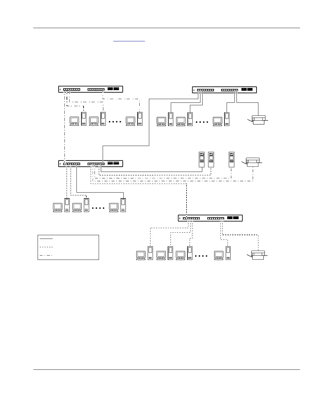
As shown in Figure 1-10, switch SW1 is configured with multiple VLANs: ports
7, 15, and 16 are in VLAN V1; ports 2, 4, 10, and 14 are in VLAN V2; and ports
1, 11, and 12 are in VLAN V1+V2.
Figure 1-10. VLAN configuration spanning multiple BayStack 350 switches
Switch SW1 can connect to switch SW2 because all of the ports on switch SW2
are configured in a single VLAN (VLAN V1). The same is true for switch SW3
where all of the ports are configured in a single VLAN (VLAN V2). In both of
these cases, the connection port from switch SW1 matches the configuration of
the other switch. The connection to switch SW4 is also valid because, in this case,
there is no longer a distinction between VLANs V1 and V2. VLAN V1+V2 is, in
effect, a single VLAN that contains both broadcast domains.
BayStack 350T switch (VLAN V2)
V1
SW3
SW1
SW4
SW2
V2
V1
+
V2
V1
+
V2
VLAN V1
VLAN V2
VLAN V1
+
V2
Key
BayStack 350T switch
(VLAN V1 + V2)
BayStack 350T switch
(VLAN V1 + V2)
100 Mb/s
BayStack 350T switch (VLAN V1)
622EF