Chapter 8. Lithography
201
8.3.2.1. Preliminary Scanning and Selecting Lithography
Region
Before performing the electrical lithography, take a testing scan in a semicontact mode
over the maximum scanning area.
NOTE. The preliminary scan can be taken with a contact technique as well, but this can
result in noticeable degradation of the conductive layer of the probe tip. This will lower
exposure level to the sample and expand the area under the tip undergoing exposure.
In the acquired scan, select a region for lithography. Take a scan of the selected region by
Kelvin Probe Microscopy (see i. 7.3.2 on p. 110).
Selecting the lithofraphy regions for charge lithography
Charge lithography will be explained with a GaAs sample and a probe of NSG01/TiN
model. Charge lithography will cause accumulation of electrical charge in the subsurface
layer under the exposing tip.
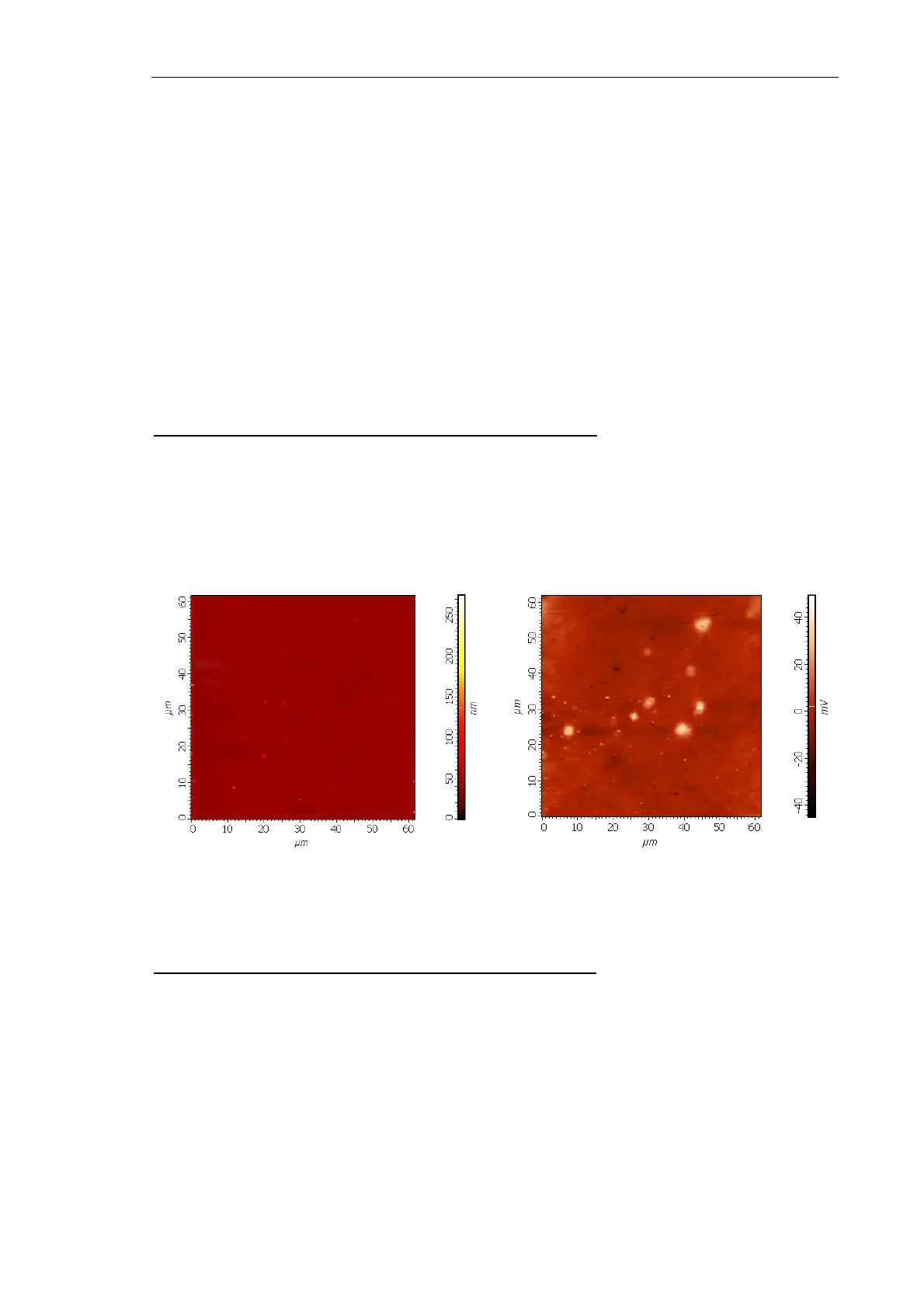
Preliminary scanning provides the surface topography and the surface potential distribution
of the region selected for topography (Fig. 8-58).
Fig. 8-58. Sample surface before lithography
left – topography; right – surface potential distribution
Selecting the lithofraphy region for current lithography
Current lithography will be explained with a octadecyltriclorsylanum sample and a probe
of DCP11 model. Current lithography will result in changing surface properties of the
sample monolayer. The surface portions exposed to voltage will transform from
hydrophobic to hydrophilic, thus providing modulation of friction and contarast for Lateral
Force Microscopy.
Preliminary scanning provides the lateral force distribution (LF signal) of the region
selected for topography.