11
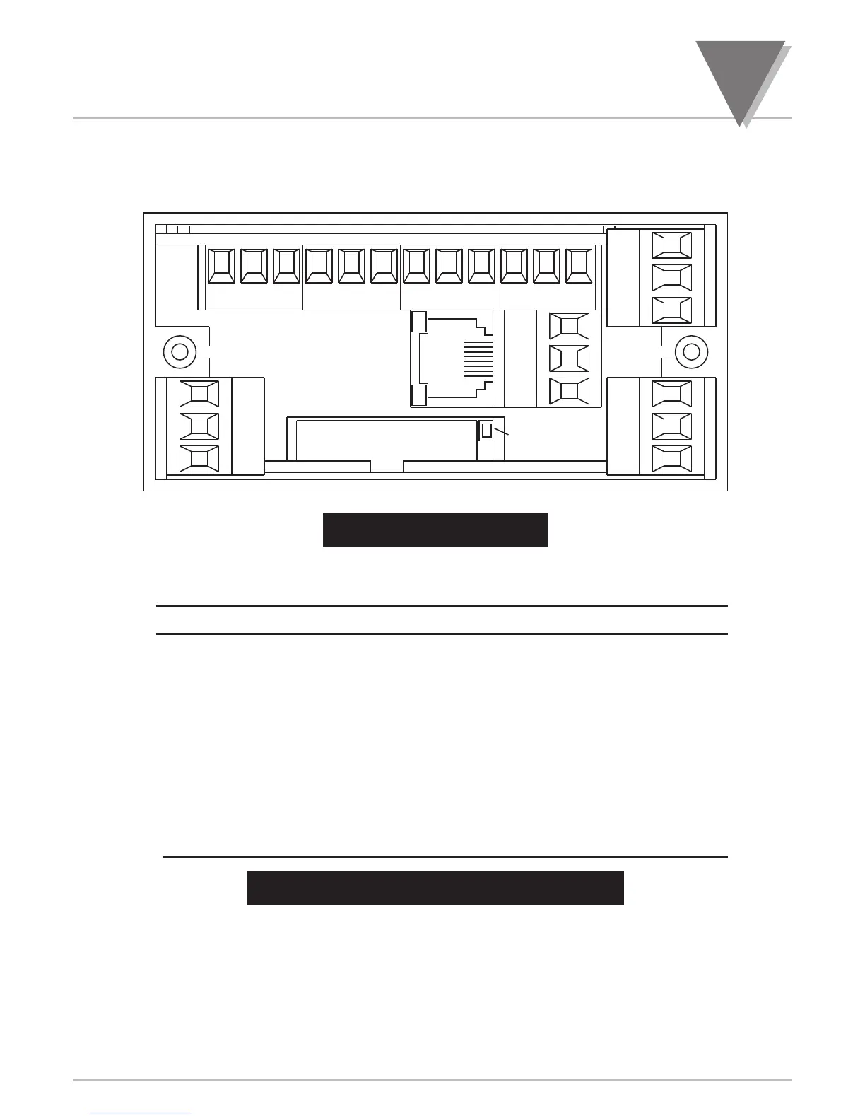
Figure 4-3 shows the rear of the meter with the optional 4-relay output board, ethernet board and
analog output board installed.
Figure 4-3. Rear View
CONNECTOR # DESCRIPTION
P1 AC Power Connector or DC Power Connector
P2 External I/O Connector
P3 Input Connector
J4 Optional RS-232/RS-485 or Ethernet Connector
P5 Optional Analog Output Connector
P6 Optional Form-C Relay #1 Connector
P7 Optional Form-C Relay #2 Connector
P9 Input Connector
P18A Optional Form-C Relay #3 Connector
P18B Optional Form-C Relay #4 Connector
Table 4-1. Rear Connector Descriptions

 Loading...


